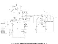
I am in the process of testing the attached KT88/6550 PP amp; however, I am not really clear about how can you tell the feedback is actually negative or positive before you actually apply and play with the feedback network. Here is the thing that confused me: From what I read from text book or searching through the web "Negative feedback occurs when the feedback signal is 180 degrees out of phase with the input signal, effectively reducing the overall gain of the amplifier. Positive feedback, on the other hand, occurs when the feedback signal is in phase with the input signal, amplifying the input and potentially leading to instability"
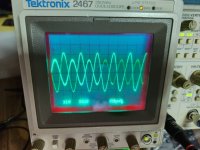
However, from LTSpice simulation it's opposite to what it said. Simulation indicated that both Input and Output signal are on the same phase for the feedback to work. The attached files showed the actual KT88 that I am currently testing with snap shot of input (Vin) and output (Vout) are out of phase for now.
Can I go ahead and apply the global feedback network or I need to swap the wirings for Vout to be in phase with Vin?
I just wanted to make sure since I don't want to ruin a brand new output transformer. Thanks in advance.
Attachments
Not sure if I understand your question/problem correctly. But perhaps the following is of use.
The first stage in your schematic operates with cathode bias. So, the cathode voltage is positive with respect to the control grid (and as a logical consequense, the control grid voltage is negative with respect to the cathode).
Now imagine part of an input signal on the control grid going upward/positive.
This will cause the voltage difference between the cathode and the control grid to decrease.
So, for feedback applied over (part) of the (not bypassed!) resistance in the cathode lead to have a negative (so, 'input signal opposing,) effect, it has to also go positive, since it has to counteract the decreasing voltage difference between cathode and control grid.
Just to prevent a possible misunderstanding: Of course this effect will only be negative (so 'input signal opposing) as long as the amount of feedback stays below the amount of input signal.
Depends on how the output transformer is internally connected, and how it is wired into the circuit.
Also you may require additional compensation to prevent oscillation at high frequencies,
more correction than just the 200pF capacitor across the 1150R feedback resistor.
But comparing the mid-frequency input and output waveforms in your schematic's topology,
the output signal polarity (not "phase") should be the same as the input,
if the feedback resistor goes to the top of the 75R input stage cathode resistor.
So reverse the connections just after the second stage, either before or after the 0.18uF coupling capacitors.

You need to draw the negative feedback parts, and connections. the same secondary output can be negative feedback or positive feedback, depending on which tube, and which element(grid or cathode) that you apply it too.
Since you have a Mullard-style topology (voltage amp to long-tail pair phase splitter), IMO you have the phase-splitter connections to the output tubes reversed. Here's a classic Mullard arranged in correct phase for negative feedback:

Of course, the output transformer primaries could also need to be changed, but since currently your input and output are out of phase, you're going to get positive feedback if you hook it up as is.
Of course, the output transformer primaries could also need to be changed, but since currently your input and output are out of phase, you're going to get positive feedback if you hook it up as is.
That is entirely possible. The important point is that to be negative feedback, the output decreases when the feedback increases, ie it works to lower the gain. You have a choice of where to pick off the feedback signal and where to apply it so that this works correct. The relationship between input and output phase is not directly of importance, although it does influence your options as to connection of the feedback loop.Simulation indicated that both Input and Output signal are on the same phase for the feedback to work.
Jan
Your simulation is OK, but the actual circuit you measured has a polarity swap somewhere. Try swapping one end of the coupling capacitors that go to the output tubes.
The reason for your confusion about feedback and reverse polarity is due to the fact (and someone please correct me if I'm wrong) that the feedback in this instance is applied to the cathode of the input stage. If I hook up one of my Williamson amps to a scope, the input signal and the output signal are in phase with each other, so I'm getting negative feedback. In your case the scope shot shows a reversal of phase, which will produce positive feedback.
I think I have that right! ;-)

Figure 31: Basic schema for global negative feedback.
Global negative feedback is obtained by feeding the attenuated output signal back to the cathode of the input stage vacuum tube. If the output signal and the input signal have the same phase, the first is subtracted from the second, reducing distortions in the amplified signal. The voltage divider composed of the resistors R1 and R2 has the effect of attenuating the output voltage used as feedback. The capacitor Csn forms, with resistor R1, a step network to adjust the feedback signal phase to guarantee stability.
I think I have that right! ;-)
Figure 31: Basic schema for global negative feedback.
Global negative feedback is obtained by feeding the attenuated output signal back to the cathode of the input stage vacuum tube. If the output signal and the input signal have the same phase, the first is subtracted from the second, reducing distortions in the amplified signal. The voltage divider composed of the resistors R1 and R2 has the effect of attenuating the output voltage used as feedback. The capacitor Csn forms, with resistor R1, a step network to adjust the feedback signal phase to guarantee stability.
The old problem with phase on either output tranny primary/secondary connections. If the secondaries are the tapped type then the connections on primary side may have to be reversed.......my amp test for this is to set signal source into the mV region, disconnect the GNFB so one gets a reasonable output into dummy loat, note it; then attach a 47K-100K resistor to the GNFB to the output and observe if the output voltage actually rises or decreases. It´s the decrease one is after, then go ahead and connect the correct value. Too low a value resistor (47K-100K) will increase towards positive feedback, into oscillation.
Le bench baron
Le bench baron
Yeah, this process has always been done empirically, meaning you try it one way and if it wirks right great if it doesn't then you got it in backwards (out of phase) and you simply switch which tube each end of the primary connects to.
If you blow up an output transformer doing this then your output transformer was inadequate for the job anyways.
often times the lead outs are mislabeled anyhow and you've got to be able to work through it and end up with a functional amplifier..
If you blow up an output transformer doing this then your output transformer was inadequate for the job anyways.
often times the lead outs are mislabeled anyhow and you've got to be able to work through it and end up with a functional amplifier..
This is the reason I double check the o/p tranny windings beforehand.......a .double trace scope excellent for the basic phasing, so long one hasn´t the invert button depressed on one channel...... No need to explain further !
You won't blow up an output transformer, but could blow a speaker if you have one connected...
Grid is an inverting input, cathode is a non-inverting input. There is no real standard for transformer primary-secondary polarity, but as mentioned, it can be measured with a dual trace scope (both channels triggered from same input). You might have to swap drivers to have the output polarity correct (0 Ohm tap grounded)
Grid is an inverting input, cathode is a non-inverting input. There is no real standard for transformer primary-secondary polarity, but as mentioned, it can be measured with a dual trace scope (both channels triggered from same input). You might have to swap drivers to have the output polarity correct (0 Ohm tap grounded)
The theoretical problem causes me so much grief that I no longer bother worrying about it. I connect one amplifier one way, and the other, the other. That makes one definitely wrong and it's easy to see which one it is and correct it.
There was a time when a tech audio guy could recite the properties of series-series, series-shunt, shunt-series and shunt-shunt feedback.
Long time ago ...
Jan
Long time ago ...
Jan
- Home
- Amplifiers
- Tubes / Valves
- Global Negative Feedback in KT88 PP amp question