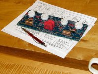
I managed to buy this circuit board along with a build guide, but of course, I have misplaced it and I need it to complete the build. The board says Aikido Glassware 2007 rev C. and the board is meant to support 6SN7 tubes as one of the possible tubes that could be used in it. There are 4 tube sockets. and the board is green but that may not matter so much. Perhaps you have an old manual that you would part with for a few bucks for your time, or even make a copy.
Last edited:
Wow! That was quick! It took Lassie much longer to come home in the book. Anyway, yes, this should be a great start for confirmation of some parts and continuing this project. I will print it out and review. Thank you, Greg
Probably the resistors and capacitors are mostly the same.
"This latest Aikido PCB does incorporate a few small improvements, such as the two output coupling capacitors (which I deem essential) and the ability to be configured as an Aikido Push-Pull circuit, which is perfect for those wishing to build a tube headphone amplifier for high-impedance cans."
"After bringing the Aikido noval stereo PCB into its E revision, where the high-voltage power supply capacitors are pure polypropylene, with no electrolytic capacitors, I was eager do the same to the Aikido octal stereo PCB; moreover, I set the PCB up just like noval PCB, where each channel gets its own separate heater power supply." https://www.tubecad.com/2018/05/blog0423.htm
I had this tagged for a line level pre in this build, but I did notice that not only does the circuit use output capacitors, there is a way to switch from one type of output capacitor by means of a switch. That may be one of the revisions. Either way, I have most every part mounted, and now I have to pony up for a power supply (probably the PS21). Last time around I used two transformers. One for the heaters and the other for the B+.

Another option might be the VTA SP-14 PC Board. An Aikido circuit with built in regulated power supply. A bit spendy but for me it was worth it. https://www.tubes4hifi.com/SP14.htm
I did find a Mono Octal Rev B 5/2007 guide if that would help. Let me know and I will scan and post.
Yes, I would like to compare it to what I have documented so far. There certainly have been changes.
You will be very pleased with this build, if you decide on the 6SN7 version. This has been in my system since I completed it last year - like you, I have had the pcb for years now. However, use the best 6SN7 tubes you can find/afford.
Mine has a regulated B+ supply and regulated filament supply.
Mine has a regulated B+ supply and regulated filament supply.
Out of curiosity, did you use separate transformers, one for each? It was just a 'theory' of mine that there would be separation between the voltages. Sound pretty silly now that I typed it, but I had an extra transformer for the filaments and decided to just get a separate B+ transformer.
What B+ voltage did you run the 6SN7 tubes at? I know that they would have a range, and John mentioned that a higher B+ might be a bit better sounding at the expense of tube life.
Last time around, I used a PS21 Broskie power supply. Likely will go that route again, but it is more money than I care for. I just know that a power supply isn't the place to cut corners.
Last time around, I used a PS21 Broskie power supply. Likely will go that route again, but it is more money than I care for. I just know that a power supply isn't the place to cut corners.
I know its around here somewhere.... Looking... I'll scan and send it to you as soon as I find it. Plus I'll try to dig up info on the section that I know is incorrect.Yes, I would like to compare it to what I have documented so far. There certainly have been changes.
Funny that you mention something being incorrect. I had the same issue with a GlassWare phono pre that I finally had to send off to someone that could actually find and correct the problem. The actual mistake was right on the circuit board. In spite of all of that, It now sounds incredible, but I would never put that much effort and money into something like that gain.
Yes, sorry I now realize that I have revision F, not E. The problem was mislabeled resistors (R13 and R14) on the circuit board itself. The manual itself is correct (which I am still looking for).