Maybe this needs clarifying. In a triode, the potential gradient is only made of straight lines if the grid pitch is so fine that in this limit the grid itself becomes a flat sheet of metal. For any practical triode the gaps between the grid wires mean you will always get curvature in the potential gradient, even in the absence of space charge. With a sufficiently negative grid, and with sufficient gaps between wires, the gradient will become a J-curve when drawn between the wires even without space charge (e.g. Dow fig. 4d).More importantly, as Bigun pointed out, for a planar diode, and a planar triode with a close pitched grid, the curve can only be straight lines if there is no electron cloud.
According to Herrmann & Wagener (1951) p111, pure electrostatic cathode stripping requires a field strength in excess of 4MV/m. No receiving valve gets remotely close to that, even with the most generous estimates. Unless that is, you manage to pull the grid very positive, which CAN happen in DC-coupled circuits when first switched on. This is a well known problem that really will cause arcs, hence the grid-cathode protection diode added to some circuitsQuite possibly, after all it doesn't seem to happen in practice. How do you know grid/anode field strengths that arise in practice in domestic valves, BTW, depending much on flatness of cathode surface according to Harmmann/Waganer ?
Last edited:
Actually, 40MV/m, ie 400kV/cm in the overview in chapter 1 p9 et seq ! Implied in overview narrative is that such issues might arise in valves where flatness of the cathode is at issue, the hazard being worse for very flat cathode coatings. I could only imagine that grid wires might sometimes be physically in contact with the cathode surface? But that narrative highlights field strength at the cathode surface as first on the list of factors limiting commercial applications of oxide cathodes. And suggests delaying B+ during warm up to mitigate, for better or worse it's there in the text. However, as we know in practice any hazard of not delaying B+ at warm-up in domestic valves is at best tenuous in practice, and apparently inconsequential based on decades of emperical experience AFAIK. So whether 'vaild' is highly questionable IMO - and all I'm supposing is that this reference might plausibly be the origin of advice which led to the whole controversy of B+ sequencing. Which seems to otherwise lack discussion in serious technical literature.According to Herrmann & Wagener (1951) p111, pure electrostatic cathode stripping requires a field strength in excess of 4MV/m. No receiving valve gets remotely close to that, even with the most generous estimates!
Last edited:
Yes, I agree.Maybe this needs clarifying. In a triode, the potential gradient is only made of straight lines if the grid pitch is so fine that in this limit the grid itself becomes a flat sheet of metal. For any practical triode the gaps between the grid wires mean you will always get curvature in the potential gradient, even in the absence of space charge. With a sufficiently negative grid, and with sufficient gaps between wires, the gradient will become a J-curve when drawn between the wires even without space charge (e.g. Dow fig. 4d).
Maybe this needs clarifying. In a triode, the potential gradient is only made of straight lines if the grid pitch is so fine that in this limit the grid itself becomes a flat sheet of metal. For any practical triode the gaps between the grid wires mean you will always get curvature in the potential gradient, even in the absence of space charge. With a sufficiently negative grid, and with sufficient gaps between wires, the gradient will become a J-curve when drawn between the wires even without space charge (e.g. Dow fig. 4d).
Note that in practice sufficiently close pitched grids to give virtually no stretched rubber sheet effects are not continuous flat sheets. Such grids are not used in audio tubes, where the pitch is obvious to the naked eye, but are used as accelerating grids/anodes in some CRT's. I have an old CRT electron gun in my personal "mini-museum". Originally the grid, about 2.5 cm square, looked like a piece of glass, the pitch and wire guage was so fine. Testing with an ohmeter showed it very conductive. It's now been exposed to the air for 20 years, and it now looks and feels like very fine hair.
Maybe this needs clarifying. In a triode, the potential gradient is only made of straight lines if the grid pitch is so fine that in this limit the grid itself becomes a flat sheet of metal. For any practical triode the gaps between the grid wires mean you will always get curvature in the potential gradient, even in the absence of space charge. With a sufficiently negative grid, and with sufficient gaps between wires, the gradient will become a J-curve when drawn between the wires even without space charge (e.g. Dow fig. 4d).
When you consider that in audio tubes the grid pitch is so coarse as to be obvious to the naked eye, yet cut-off can occur with a little as 4 volts or so, and even the 20 to 30V required in some power tubes, it is not hard to see that a pitch fine enough to all but eliminate the stretched rubber sheet effect (ie the curvature of potential between grid wires) is readily achievable without needing a continous metal sheet. A grid winding pitch around the 10's of um is quite sufficient, and with frame grid methods the wire gauge can be fine enough to still have plenty of gap for electrons to go thru.
Member
Joined 2009
Paid Member
As I said before, mathematics is THE language of physics, if we want to discuss seriously about physics, “math” is unavoidable, unless we talk about philosophy.
I consider it a strength that a physicist be able to express ideas and explain the nature of things without recourse to maths. Some of the most eminent physicists demonstrate this ability.
Math is a language of Physics, but not an exclusive language. It facilitates great things in Physics that can not be effectively achieved without it. Math appears to be a necessary tool. But I don't believe it is a necessary language for communication of the ideas and conclusions.
The reason for 190 posts without more convincing conclusions is just that, too much philosophy and so less physics. IMHO
In my opinion, it is a lack of clear understanding and clear explanation that makes a discussion like this difficult - but the real reason for 190 posts is because people like to talk, to debate and to enquire.
BTW, my doodles are not intended as physics, but I am just a TV repairman, and most of you are electronic engineers.
You sound like you feel a TV repairman is less than an engineer ? - I don't agree. Some engineers couldn't repair a TV if their dinner depended on it ! and yet the TV repairman brings clear value to the family that owns it, and a lot of pleasure to the children watching it.
My original assumption is only a rough estimate, because it must be compared the de Broglie wavelength
Are you sure it 'must' be compared ? - particle-wave duality is a very powerful idea in physics but for the purposes of understanding interactions in the vacuum tube I suspect that we are well served with the particle approach rather than the wave approach.
Last edited:

Don't start trading insults or you will find penalties being handed down. Argue your points on technical merit, and if for whatever reason you feel its going nowhere then just gracefully retire from the thread.
Interestingly such fields are discussed in that section in the context of 'sparking' - which is a separate cathode degradation mechanism from the one mentioned in the overview (page 9)..... both mention sequencing of B+ & heaters, as a mitigation or influence. Pages 106 - 112.According to Herrmann & Wagener (1951) p111, pure electrostatic cathode stripping requires a field strength in excess of 4MV/m. No receiving valve gets remotely close to that, even with the most generous estimates. Unless that is, you manage to pull the grid very positive, which CAN happen in DC-coupled circuits when first switched on. This is a well known problem that really will cause arcs, hence the grid-cathode protection diode added to some circuits
According to the text, sparking seems to have a complex process. Putting aside high reverse voltage blocking diode applications, there seems to be a more general cathode degradation process which works as follows in sequence if I understand it correctly:
Oxide cathode naturally has hot/cold spots
Hot spots get hotter
Oxide coating locally evaporates to gas
Gas ionises (+) significantly, enough to significantly deplete space charge locally (!!)
Cathode current increases, hot spots get hotter
Hot spots become local cathode damage via evaporation, ion sputtering
If circuit limits Ik, there is no immediate anode - cathode just a local flare
Otherwise anode-cathode arc forms, perhaps next time powered up
Cathode becomes seriously damaged
The link with warm-up according to the text is that hot/cold spot formation is worse at low cathode temperatures, and max risk is during warm-up if B+ and heater are simultaneously applied. I think its implicit that high voltage applications have higher risk.
But I think there seem to be two steps here: 1) formation of local hot spot cathode damage 2) actual arcing. The former apparently might be mitigated by sequencing B+/heater ?
Is this a known and documented phenomenum ?
BTW in a previous post I mooted that high fields might arise from grid wires in contact with oxide cathode - but I realise that's impossible because oxide cathodes conduct at 1000 C, of course. So really high fields only seem likely in high voltage applications such as pulse, with blocking potentials in the 10s of kV I think.
Last edited:
......<cut>
Cathode current increases, hot spots get hotter
Hot spots become local cathode damage via evaporation, ion sputtering
If circuit limits Ik, there is no immediate anode - cathode just a local flare
Otherwise anode-cathode arc forms, perhaps next time powered up
Cathode becomes seriously damaged
The link with warm-up according to the text is that hot/cold spot formation is worse at low cathode temperatures, and max risk is during warm-up if B+ and heater are simultaneously applied. I think its implicit that high voltage applications have higher risk.
But I think there seem to be two steps here: 1) formation of local hot spot cathode damage 2) actual arcing. The former apparently might be mitigated by sequencing B+/heater ?
Is this a known and documented phenomenum ?
BTW in a previous post I mooted that high fields might arise from grid wires in contact with oxide cathode - but I realise that's impossible because oxide cathodes conduct at 1000 C, of course. So really high fields seem likely in high voltage applications such as pulse, with blocking potentials in the 10s of kV I think.
It is certainly known and documented in rectifiers.
The combination of high voltage and absence of current-limit will cause actual arcing, as anyone who has crash-started directly-heated rectifiers into an excessive load can verify.
Here is evidence for that, in the RCA 5R4WGB data sheet, where we are warned to preheat the filaments for ten seconds, if high voltage and a heavy load is present.
Attachments
Yes. And if the issues were already settled, there wouldn't be discussion and debate I think.In my opinion, it is a lack of clear understanding and clear explanation that makes a discussion like this difficult - but the real reason for 190 posts is because people like to talk, to debate and to enquire.
Just to play devil's advocate, are you sure you can have space charge in a triode at cut-off? Is not the point at which the space charge 'retreats into the cathode' the very definition of cut-off? Because, if a some space charge did still exist, that very fact means electrons are still attaining enough energy to leave the cathode and therefore, statistically, some of them will also attain enough escape energy to overcome the potential well in the grid plane and so reach the anode, hence the valve is not fully cut off (?)
If cut-off means strictly zero anode current then you may be right. This would require a very negative grid bias to ensure that even the most thermally energetic electrons are kept at bay. I suspect that cut-off really means 'the point at which anode current becomes very small' (with perhaps an exponential reduction for further negative grid bias?) in which case a space charge could still exist.
From Richardson-Dushman equation
J0 = A0 T² exp ( - e φ / k T ) … (1)
If you apply a retarding potential Vr
J = A0 T² exp [ - e (φ + Vr) / k T ] = J0 exp ( - e Vr / k T ) … (2)
If the cut-off condition were J=0, it should be Vr → ∞
As J≠0, there is always a contribution from the cathode to the cloud.
Hence, DF96 is right, and cut-off really means the point at which anode current becomes very small.
I consider it a strength that a physicist be able to express ideas and explain the nature of things without recourse to maths. Some of the most eminent physicists demonstrate this ability.
To the general public, or to his granny; among them they “talk” with maths and words.
You sound like you feel a TV repairman is less than an engineer ?
No, I mean that most forum members involved on this discussion have enough background to read and understand equations, it is like riding a bike, you never forget.
On the other hand, has been cited a lot of authors, without mentioning books’ titles, I think that an equation would be a minor “offence”.
Are you sure it 'must' be compared ? - particle-wave duality is a very powerful idea in physics but for the purposes of understanding interactions in the vacuum tube I suspect that we are well served with the particle approach rather than the wave approach.
You suspect well, and that is precisely the idea, if you want to describe electron interactions with matter classically, as if they were marbles or billiard balls, you want its particle-like behavior, hence, for the electron, its de Broglie wavelength must be negligible compared with interatomic distances, i.e. at high enough energies.
Last edited:
Thanks, that fits I think. Presumably would be similar in oxide cathode power triodes/pentodes, unless it's somehow the high blocking voltage that's involved, as might be in actual arcing? I'd think the formation of hot spots might be similar, without the arcing perhaps?It is certainly known and documented in rectifiers.
The combination of high voltage and absence of current-limit will cause actual arcing, as anyone who has crash-started directly-heated rectifiers into an excessive load can verify.
Here is evidence for that, in the RCA 5R4WGB data sheet, where we are warned to preheat the filaments for ten seconds, if high voltage and a heavy load is present.
I have some private correspondence, from 2012, in a discussion of filament heating (some will know of my interest in this subject) with a vendor of current-production valves, where a similar warning is given for power valves.
The explanation given in this case:
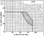
- that the cathode surface warms up quite unevenly, and if supply voltage is applied without large negative bias at this time, high current-peaks at particular locations can give arcs, or in lesser cases silent erasure of high spots on the surface.... And that this can have a strong influence on the lifetime of new power valves.
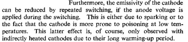
In other words, the same explanation as Herrman & Wagener provide for the mechanism of "sparking", where on pp119, it is asserted that cold application of anode voltage reduces emissivity.
If this material is of great interest, I may ask my correspondent to allow me to reprint the paragraphs.
The explanation given in this case:
- that the cathode surface warms up quite unevenly, and if supply voltage is applied without large negative bias at this time, high current-peaks at particular locations can give arcs, or in lesser cases silent erasure of high spots on the surface.... And that this can have a strong influence on the lifetime of new power valves.
In other words, the same explanation as Herrman & Wagener provide for the mechanism of "sparking", where on pp119, it is asserted that cold application of anode voltage reduces emissivity.
If this material is of great interest, I may ask my correspondent to allow me to reprint the paragraphs.
Attachments
Member
Joined 2009
Paid Member
Do you know if these guys are recycling what they read in Herrman & Wagener or instead have conducting experiments with the tubes from their factory (and at what operating voltages / electric field strengths) ? - I guess it could be a commercially sensitive item since from what we've read, the better the quality of the filament and coating adhesion etc. the less likely that sparking is going to be an issue.
Note also that sparking involves "considerable evaporation of the coating" and the "evolution of appreciable quantities of gas".
pp 108 of H & W.
This gas will degrade the performance of the valve quickly enough, in addition to the reduction in lifetime brought on by the damage to the coating.
pp 108 of H & W.
This gas will degrade the performance of the valve quickly enough, in addition to the reduction in lifetime brought on by the damage to the coating.
Do you know if these guys are recycling what they read in Herrman & Wagener or instead have conducting experiments with the tubes from their factory (and at what operating voltages / electric field strengths) ? - I guess it could be a commercially sensitive item since from what we've read, the better the quality of the filament and coating adhesion etc. the less likely that sparking is going to be an issue.
Or does a coating with greater emissivity cause ever more rapid heating of hot-spots? I believe it does, since it is a kind of thermal-runaway effect.
Again, please see H & W pp108, bottom paragraph.
In this case Power valves, in new condition, with very high emissivity, will suffer more severely, if sparking is allowed to develop.
High emissivity is usually considered a good thing, especially in terms of usable lifetime.
Very interesting, Mr Coleman. Personally, yes it is of great interest and a reprint of the text would be great, since the gist seems very much in line with H/W 1951 text.I have some private correspondence, from 2012, in a discussion of filament heating (some will know of my interest in this subject) with a vendor of current-production valves, where a similar warning is given for power valves.
The explanation given in this case:
- that the cathode surface warms up quite unevenly, and if supply voltage is applied without large negative bias at this time, high current-peaks at particular locations can give arcs, or in lesser cases silent erasure of high spots on the surface.... And that this can have a strong influence on the lifetime of new power valves.
In other words, the same explanation as Herrman & Wagener provide for the mechanism of "sparking", where on pp119, it is asserted that cold application of anode voltage reduces emissivity.
If this material is of great interest, I may ask my correspondent to allow me to reprint the paragraphs.
Yes, I get that.Rod Coleman said:In this case Power valves, in new condition, with very high emissivity, will suffer more severely, if sparking is allowed to develop.
Member
Joined 2009
Paid Member
Fortunately, for the voltages that I use in my tube amplifiers this isn't an issue - the field strength is insufficient to cause sparking. And I'm not brave enough to play with kV transmitter tubes !
I have some private correspondence, from 2012, in a discussion of filament heating (some will know of my interest in this subject) with a vendor of current-production valves, where a similar warning is given for power valves.
If this material is of great interest, I may ask my correspondent to allow me to reprint the paragraphs.
Rod, it IS of great interest. Please ak them. What specific tube types does your correspondent's advice apply to?
- Status
- Not open for further replies.
- Home
- Amplifiers
- Tubes / Valves
- Getter heater & B+ sequencing ?