But you know the difference between theory and praxis?.
You do remember what happened to Praxis, right? Like a very large overloaded germanium transistor.
“We cannot confirm the existence of Praxis!” (Star Trek 6).
I build my own speakers from scratch, including winding voice coils.But you know the difference between theory and praxis? Theoretically none😛
But seriously - I know this hype around excessive damping since the seventies. It is a myth, and utterly boring. And I know that not one single person believing the contrary can be convinced by arguments.
A 2" 8 ohm 10mm winding height voice coil is made out of **15 meters** 😱 of **0.20mm** 😱 diameter enamelled wire, with a DCR around **6.5 ohm** 😱
Which is always in series with the speaker motor (solenoid and magnetic system) and for clarity can be modeled as a "perfect" electromagnetic motor fed through a 15 meter long hair thin wire..
Or to make it more of an "everyday example", imagine cabinet 7.5 meter away from amp, fed through a an 2x 0.032 mm^2 section wire.
Even humble 2 x 1mm (AWG#18) lamp zipcord is "Monster Cable" compared to that.
Maybe now you´ll understand my absolute DESPISE for ALL "Cable Threads" 🙄
And lack of interest for "High Damping" ones.
Now when damping falls below, say, 0.2 or "worse" , going all the way to constant current drive, *then* things start being interesting, but .... arguing between 0.1 and 0.0000000001? .... pfffftt!!!!!
Last edited:
Adding a tenth or two of an ohm would never be noticed. Half an ohm to an ohm, maybe you’d notice the cabinet starting to get detuned. You would as likely notice a change in the crossover Q, which would affect phasing between the mid and tweeter, and you’re more sensitive to those frequencies than you are the bass.
When the voice coil heats up under drive the effect is much more pronounced than anything that happens with the amp. At the full power that it can handle, a speaker’s voice coil resistance nearly DOUBLES - just the properties of copper wire at 200-250C, where things would normally break.
Some amplifiers do exhibit a huge increase in output impedance when they are driven to clipping. This results in sounding very muddy when overdriven, more so than with a better amplifier. This is unfortunate, because this kind of JUNK amplifier is what they put in powered subwoofers - the part of the reproduction chain that it does the most damage to. But it’s all about cheap.
Very easy to add one. It would probably scare people to see just how often you drive to clipping and never notice, even at moderate listening levels.
That's not my experience, at least not with commercial music releases (including classical music).
I have had a clipping LED that lights up for about 1 second after a few microseconds of clipping on my 2 times 20 W into 8 ohm amplifier since 1994. It never lights up during normal use. It did sometimes light up during the applause when I played some completely uncompressed DIY recordings of the choir that my partner used to sing in using 86 dB @ 1 W, 1 m loudspeakers at a somewhat louder level than I normally do.
Of course it depends on a lot of things: amplifier power, loudspeaker sensitivity, listening room size and damping, what level you like and so on. See also Pano's test, A Test. How much Voltage (power) do your speakers need?
Regarding post #52: SSB seems to be a guitarist. Maybe the Ge transistor is for some fuzz box?
(But it would help to know).
Not tried to design such a thing, but it seems possible that silicon could be used with some sort of moderate (under)bias to give a Ge-like transfer curve.
Also there seems to be a following for the old four transistor, two transformer, 1W Ge amplifier among various bands.
Last edited:
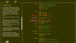
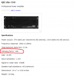
You really need to proove that THEORETICALLY in the first place cause Pioneer a-09 amp quoted by Cioffoli had a diamond buffer with no global feedback, while QSC USA 1310 is using a virtual ground relying entirely on unregulated...electrolitic capacitors .If you ever heard a QSC USA amp you know what BASE means... I doubt a guitar player will ever care about damping factors when miking a cabinet at 80 hz...Unlike you maybe i had a Kenwood ka-1000 and huge damping factors arent really what people believe they are as you always need to factor in a relay in series with the output in 99.99% of the amplifiers...Unlike your usual Crown pro stage amplifier QSC has some capacitors and at least 0.05 ohm emiter resistor in series with their woofers ....never heard of audio amps based on silicium transistors with no emiter resistors either...I assembled several Ge output power buffers along the Ciuffolli Follower lines.
I can state, that Ge power transistors allow to achieve output impedance of amplifier in the range of 0,01...0,015 Ohms without any Negative Feedback Loop !
This is absolutely not possible with Si power transistors, usually one achieves around 0,1 Ohms in the emitter follower configuration. Si transistor has theoretical limit 0,025 Ohms, but essential base region resistors is added to this value.
Main difference between Ge and Si is in valuee of intrinsic base region resistance. This parameter is well determined and explained. Ge is better conducting, therefore intrinsic resistance of the base region of Ge transistors is much lower than of Si.
Compared sound of original Ciuffolli Follower and Ge follower, the last gives better articulated bass and more "open" sound.
Attachments
Last edited:
Not getting your point exactly - but anyway, output impedance of BJT amps with some global feedback is generally lower than their emitter resistors.
Well, from time to time someone feels some very deep need to capitalize on the magic of Non feedback amplifier and today germanium transistors are the heroes cause why not?Some of them needs being sold....One day someone might feel the need to prove that 60 years old tubes and output transformers can do it cause we wont need them for their harmonics anymore one day so some other strange phenomenon will take the lead to reinforce them in our memory...
Last edited:
The theoretical emitter impedance of a transistor is 25mV (or strictly kT/q)divided by the emitter current. That should apply to Ge and Si devices. Therefore it would need a "theoretical" 1A to obtain 25milliohm output impedance.
However, as VladimirK says, the base impedance will add to this figure.
Not only that but at currents of 1A or so many transistors will be starting to see high signal injection effects which will degrade the transfer characteristic which will also increase the Vbe.
Therefore I agree in practice that 25 milliohms is not likely to be obtained with a Si device, but can Vladimir show the circuit for a Ge output stage with 15milliohms output impedance without NFB? Was this using a high current device - which may reach theoretical values better than silicon?
Is that measured under isothermal conditions?
(BTW it should be "theoretically" possible to get lower output impedance than 25 milliohms with parallelled transistors, although, of course, there will be emitter resistors to balance the current)
Last edited:
This little quest started out looking for relatively low power higher voltage Ge’s, to wanting something specifically with a low Vbe, to wanting a very low open loop output Z. I can’t figure out what we’re tying to actually build here. Is it a high current application or isn’t it?
Even if the goal really is “I want to build X using germanium transistors”, we’re not going to get anywhere with any of this until somebody solves for X.
Even if the goal really is “I want to build X using germanium transistors”, we’re not going to get anywhere with any of this until somebody solves for X.
The theoretical emitter impedance of a transistor is 25mV (or strictly kT/q)divided by the emitter current. That should apply to Ge and Si devices. Therefore it would need a "theoretical" 1A to obtain 25milliohm output impedance.
Therefore I agree in practice that 25 milliohms is not likely to be obtained with a Si device, but can Vladimir show the circuit for a Ge output stage with 15milliohms output impedance without NFB? Was this using a high current device - which may reach theoretical values better than silicon?
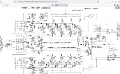
I have measure output impedance at 1 kHz 13mOhms by using this preliminary draft Ge SE output buffer schematics. It was Ge quadruplet emitter follower schematics, designed along with Ciuffoli Follower lines. Cases of all transistors can be grounded, very convenient,
Attachments
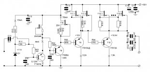
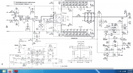
Later on, trying to improve sound further, I have replaced the first and the second Ge stages by one BC109B Si stage. Also I have substitute the D1 Zener by a resistor shunted by decent capacitors. Some base resistors have also been removed.
I should also to mention, that in this schematics, there is no problen to put several Ge output transistors V12 in parallel. For this, each V12 transistor must be loaded by its individual current source, and each collector must see the load via its individual output capacitors. Outputs of all capacitors then connected together and form common output to the load. So quite powerful SE output buffer is possible in this way. The 1T813 transistors are in fact two 1T806 chips placed on the same substrate in parallel.
At present, I use such Ge buffer with single-tube triode connected 6E6P-DRU preamp, C11 is placed at the preamp output.
Last edited:
- Home
- Design & Build
- Parts
- Germanium Transistors! Help!