For those that have never come across this there is something called 'tin whiskers' that afflicts germanium transistors.
https://www.markhennessy.co.uk/articles/vintage_transistors.htm
https://www.markhennessy.co.uk/articles/vintage_transistors.htm
As germanium transistors are not easy to get anymore, I would like to know which types would fit which positions.
According to @Mooly 's post with the spice file, AC128K for PNP and AC176K for NPN are appropriate for all positions.
Which alternatives are there? ACY21 for Q1 I think I read, any other alternatives, which can be used mostly without changes?
Any russian types?
According to @Mooly 's post with the spice file, AC128K for PNP and AC176K for NPN are appropriate for all positions.
Which alternatives are there? ACY21 for Q1 I think I read, any other alternatives, which can be used mostly without changes?
Any russian types?
I didn't measure the leakage although there should be no issues in a circuit such as with using these sort of supply voltages and component values.
The rationale behind my question was that a higher Ice0 could be / is an indicator for tin whiskers having developed, implying a higher potential risk of a failure in the (near) future.
Is that a baseless fear?
Is that a baseless fear?
Probably not baseless and certainly if you have a few devices to choose from then you can always measure and select the lowest leakage devices (and highest gain as well). Otherwise its a case of use what you have and work on any individual issues should they occur. The 'whiskers' problem I think affected mostly the AF series that were used in the front end of radios (very good HF performance) but if you have any you might have been tempted to try them as a preamp stage.
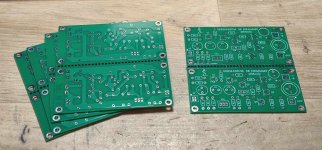
I am on the way of building this amplifier....just got the pcb's from China....thanks to @Julian RO.
I opted for a dual channel execution, with the option to split the pcb in two identical halves.
For Q1 and Q6 I will mount some sockets to choose between several candidates, for the optimum noise level.
Are the first 3 capacitors really needed in such a high value? I think I will mount a 10uF for C1, maybe a little higher for C2 and C3, based on the "not so high" loading impedance. Still I think that 22uF is largerly enough for those. I didn't see a C4 in the schematic...I will consider a C4 at the supply input.
Attachments

Are the first 3 capacitors really needed in such a high value?
No, they can be reduced. I would have kept those on the diagram simply because those are what was fitted at the time (and its good practice for documentation to reflect the original and not make untested changes).
Here they can of course be altered. The simulation shows the effect of changing values. It would be good practice to let the input cap do the LF roll off.
This shows the response with the original vs altered (a 1uF and two 10uF's)
In my case a tiny roll off before 20Hz could be wanted, I intend to use this amplifier together with a RIAA preamp for vinyl listening, maybe higher than 20Hz...I will test this.
1 uF could be too small, but in my (still untested) opinion 10 uF with 22 or 47uF willl be enough. I share here my temporary BOM....with open values for Q1 and Q6. For Q1 I have two medium power transistors from an old Polish radio, just a guess they will be low noise devices...we'll see...
1 uF could be too small, but in my (still untested) opinion 10 uF with 22 or 47uF willl be enough. I share here my temporary BOM....with open values for Q1 and Q6. For Q1 I have two medium power transistors from an old Polish radio, just a guess they will be low noise devices...we'll see...
Attachments
If we make all the caps apart from the input cap 1F (to remove their effect) then a 0.22uF for the input coupling cap gives you a -3db point of 20Hz. The simulated result agrees well with a calculated value. R3 and R4 appear in parallel as a 32k and 32k and 0.22uF give a -3db point of 22Hz. That calculation disregards the 16k input resistor.

Yes...I noticed that, too. The good thing is there's nothing to cut or re-trace.
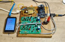
I finished assembling the amp, it seems to sound good, but this is a "breadboard" version - woodboard in fact. After a few tests I will come again with my results.
As a first impression, my player (FiiO M6) has not so much swing for the output, maybe another gain stage could be welcome here. For sure, using an output from a CD could be enough, but not a normal line level. The sound is very warm, maybe not for audiofiles, still a very pleasant sound for listening to music. In fact this is a good reason for the germanium - or tube builds. For refference sound, there are much more other options, silicon transistors opamps, dedicated circuits etc.
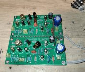
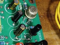
My build is made with TG50 for Q1 - I have from my childhood two salvaged Unitra transistors from an old radio, hfe=59 both. And for Q6 I used also two salvaged transistors, from an old czech reel to reel recorder, 106NU70. For Q2 I used some Romanian EFT353B transistors, they are claimed to be low noise ones. They also have high-ish gain, around 150 - a good number, I think, for Germanium devices. All the rest - Q3,4,5 are AC125, Tungsram, NOS. Gain around 80-100, relatively well matched between the two channels. The last 3 transistors run relatively hot, maybe in the final assembly I will use some metal wings for better cooling.
As you can see, I used some pins from IC sockets, for easy removal of Q1 and Q6. After tests, I will solder the final transistor choices.
The power supply is a LV'S denoiser, tailored for 6.8V output. (270R and 1K21 for the resistors around the LM317 regulator).
No detailed measurements by now, but I noticed no hiss in this build, even with Sennheiser HD650. These are very sensitive headphones, but this amplifier is not a good option for high impedance headphones, it sounds good with 16....32 ohms headphones. Now I'm listening it with Hifiman Edition XS.
I finished assembling the amp, it seems to sound good, but this is a "breadboard" version - woodboard in fact. After a few tests I will come again with my results.
As a first impression, my player (FiiO M6) has not so much swing for the output, maybe another gain stage could be welcome here. For sure, using an output from a CD could be enough, but not a normal line level. The sound is very warm, maybe not for audiofiles, still a very pleasant sound for listening to music. In fact this is a good reason for the germanium - or tube builds. For refference sound, there are much more other options, silicon transistors opamps, dedicated circuits etc.
My build is made with TG50 for Q1 - I have from my childhood two salvaged Unitra transistors from an old radio, hfe=59 both. And for Q6 I used also two salvaged transistors, from an old czech reel to reel recorder, 106NU70. For Q2 I used some Romanian EFT353B transistors, they are claimed to be low noise ones. They also have high-ish gain, around 150 - a good number, I think, for Germanium devices. All the rest - Q3,4,5 are AC125, Tungsram, NOS. Gain around 80-100, relatively well matched between the two channels. The last 3 transistors run relatively hot, maybe in the final assembly I will use some metal wings for better cooling.
As you can see, I used some pins from IC sockets, for easy removal of Q1 and Q6. After tests, I will solder the final transistor choices.
The power supply is a LV'S denoiser, tailored for 6.8V output. (270R and 1K21 for the resistors around the LM317 regulator).
No detailed measurements by now, but I noticed no hiss in this build, even with Sennheiser HD650. These are very sensitive headphones, but this amplifier is not a good option for high impedance headphones, it sounds good with 16....32 ohms headphones. Now I'm listening it with Hifiman Edition XS.
Attachments
Last edited:
After listening all night with several pairs of headphones, my musical taste says this amp is a keeper....too bad it is limited to low impedance headphones.
@Mooly : If you know and manage the simmulation software, can you upgrade this schematic to o higher supply voltage? Eventually with medium power output devices, but my demand is not for mure power, but for higher output voltage swing...I have more PCB-s for this schematic and I should try this for a voltage of 9 or even 12 volts. Can you give us some advice? I shall use maybe AC188K for the 3 output transistors...Can you give o formula for the relation between the value of R10 and the constant current?
@Mooly : If you know and manage the simmulation software, can you upgrade this schematic to o higher supply voltage? Eventually with medium power output devices, but my demand is not for mure power, but for higher output voltage swing...I have more PCB-s for this schematic and I should try this for a voltage of 9 or even 12 volts. Can you give us some advice? I shall use maybe AC188K for the 3 output transistors...Can you give o formula for the relation between the value of R10 and the constant current?
I'll have a look later...
It is the base/emitter voltage of Q5 (so around 0.18 volt for germanium) divided by R10. 0.18/3.3 gives approx 55ma.
Can you give o formula for the relation between the value of R10 and the constant current?
It is the base/emitter voltage of Q5 (so around 0.18 volt for germanium) divided by R10. 0.18/3.3 gives approx 55ma.
Why would this be the case? In LTSpice, 300 Ohms (e.g.) work fine with mW levels that would make you deaf. Of course only when using transistors in the output stage that can handle the power. The AC128K / AC176K should be able to, I think.too bad it is limited to low impedance headphones.
Last edited:
I have some AD161/AD 162 pairs from the first amplifier I made. They could make a good Germanium headphone amplifier. I have the bias thermistors too. Somewhere.
There's no need for power, just for higher output voltage.
AD162 (161 not needed here) is a little too good for (just) a headphone amp. Maybe fitted with a small output trafo or autotransformer gapped correctly in this way it could drive small computer speakers. But if we go beyond devices like AC180, we can try using my earlier proposal, a IC for power supplay used as CCS. If not an LM78xx, maybe a LM317 will do the job better. with an increased supply voltage.
AD162 (161 not needed here) is a little too good for (just) a headphone amp. Maybe fitted with a small output trafo or autotransformer gapped correctly in this way it could drive small computer speakers. But if we go beyond devices like AC180, we can try using my earlier proposal, a IC for power supplay used as CCS. If not an LM78xx, maybe a LM317 will do the job better. with an increased supply voltage.
So a 12v and 18v version. Only proved in simulation. The 2k2 after the volume control is actually because I used a linear pot rather than a log (to fake the law) and these show that removed. The pot is turned up higher to get more level in these sims. Remember to check that you do not exceed the Vce rating for any of the transistors you might use.


And 18 volt:


And 18 volt:
Attachments
Thank you, @Mooly , the 12V version seems perfect, 18V seems a bit too much. Maybe that could be a good idea with output trafo to drive also some small speakers....
I'm aware of the Uce, for such schematic I will "sacrifice" some AC171 I was keeping for a bigger project. For Q1 I will experiment with more transistor types, that old Polish transistors seem to be extreme quiet, unfortunately they are the only 2 I have.
After the first attempt I used a strap instead the potentiometer, shorting the VR1A and an open VR1B, I forgot about the 2k2 one...for the initial test I think I will make a direct link from C2 to the base of Q2.
- Home
- Amplifiers
- Headphone Systems
- GERMANIUM Single ended Class A Headphone Amp.