os, both sides heat up equally at full bias (100) but they don't heat up equally at the lower bias settings.
Well, that is good , at least you can get balanced sides at full bias. I ran your present stealth at the 50 mark after the amp change and both sides heated up. I do have the matching amp to yours but shipping and then you swapping channels would be awkward , I will
fix #3 for free , you just send the parts.
I hope this will compensate.
OS
EDIT - D0N SAYS THIS PROBLEM IS NOW FIXED
Last edited by a moderator:
I definately don't want you to fix #3 for free! You've done a great job. I am in awe of your capabilities! #3 sat in a well known shop in california for 5 years... 5 years! The tech gave up and said he couldn't repair it. I sent it to you and you got it working in a week or 2. 😱
You mentioned sending me a BOM for the materials you need for stealth #3. I may have missed it... but I haven't seen that yet.
I'm ready to zap the funds over, just let me know what you need. I can't send you the parts because I don't know what you need. I can send you funds and you buy the parts or you can send me a parts list and I'll buy em and then send em to you. However you want to work it just let me know.
I sent you an email about stealth #2. We'll work it out.
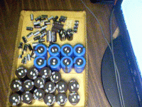
So begins the recapping of this beast , all the best ... 105c @ 100v X 132,000uf !!
stage 1 (the power supply /recapping - inrush thermistors), will be really labor intensive requiring a lot of solder and just massive physical replacement (attachment 1). Once I have all the nicely recapped supplies - (+ -75v main amps) , (+- 40v - VAS's) (+- 30v and +- 12v /5 V auxiliary supplies) that is alot of supplies - 68 caps... I will simulate the blown Voltage modules on LT to determine their method operandi... 🙂 .
Mouser electronics is wonderful , bubble wrapped all the big caps , shipped lightning fast , A highly recommended source.
OS
Attachments
that's a boat load of caps!
The big blue ones (8 X10,000u @ 80v /105c CDE)and the medium/small ones came today. I will try to replace as many as possible with my 25 watt iron + solder wick (I hope I have enough - 2/ 5' rolls). I might need to go for a 40w iron for the 10 gauge "electric range wire" the stealth uses almost anywhere.
The genesis stealth seems to be a mark levinson design with it's strings of diodes and use of current mirrors everywhere. By knowing this and having the schematic , I am sure this will be "doable".
Os
That amps just nuts, haven't checked out it's actual schematic but 720W classA!!!! at one point I considered building a 50W class A and decided it was too crazy. Also amazing how much tech has moved forward as it's whole cpu card could be replaced with a single $2 micro nowerdays. Although the adjustable bias is clearly needed just to avoid the crazy electricity bills.
actually 1.6KW both channels- 2 ohms !!That amps just nuts, haven't checked out it's actual schematic but 720W classA!!!!
It is powered by the "mighty" 8088 + a flashable rom. All these years and that part of it still works perfect (thank god)it's whole cpu card could be replaced with a single $2 micro nowerdays.
OS
Please send a copy of the schematics. Thank You.
My computer crashed a while ago and I no longer have the schematics. OStripper may have still have them.
So begins the recapping of this beast , all the best ... 105c @ 100v X 132,000uf !!
stage 1 (the power supply /recapping - inrush thermistors), will be really labor intensive requiring a lot of solder and just massive physical replacement (attachment 1). Once I have all the nicely recapped supplies - (+ -75v main amps) , (+- 40v - VAS's) (+- 30v and +- 12v /5 V auxiliary supplies) that is alot of supplies - 68 caps... I will simulate the blown Voltage modules on LT to determine their method operandi... 🙂 .
Mouser electronics is wonderful , bubble wrapped all the big caps , shipped lightning fast , A highly recommended source.
OS
Any progress updates or pics OStripper?
All done recapping / cleaning and fixing the messed up traces left behind by some one other than me !!
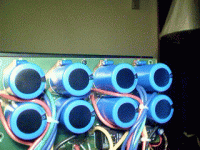
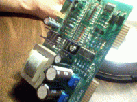
pix 1 - the easiest one to do , thick board , thick traces , never touched by previous tech - 80.000 uf CDE caps at 80V.
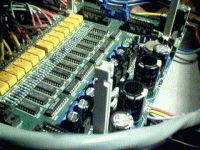
pix 2 - the input / aux. power supply board. This one also was restored to perfection (and works perfectly) never touched after it left genesis (until now). It has all the input relays/buffers ,+-5v, +-15v, +-30v, and +-42V, and holds the voltage amp boards.
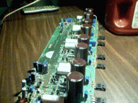
pix 3- Main amp (26,400uf per channel)... this is the heat generator (for those cold northern winters).
pix 4 - The voltage amp , these are both failed .. next I will simulate them because the schematics are vague and incomplete.
Next stage .. put all the power supplies back together and test for the correct voltages , soft start operation , etc.
All total 151,000 uf !!
OS
Attachments
Last edited:
WOW! Looking good OS! Amazing work.  You changed all the Genesis 85 Celcius caps to 105 Celcius caps. I like that! 🙂 This Stealth should be a lot more reliable now.
There are two main amp boards (L & R) being recapped (pic 3 shows one)?
Should we replace all the mosfets since we're (you're) recapping the entire amp? If there's even a hint that they should be replaced... let's do it. I'll order up whatever you need ... just say the word and I'm on it.
I still need to send the remote out so you can change the BIAS. I'll do that ASAP
 You changed all the Genesis 85 Celcius caps to 105 Celcius caps. I like that! 🙂 This Stealth should be a lot more reliable now.
 There are two main amp boards (L & R) being recapped (pic 3 shows one)?
Should we replace all the mosfets since we're (you're) recapping the entire amp? If there's even a hint that they should be replaced... let's do it. I'll order up whatever you need ... just say the word and I'm on it.
I still need to send the remote out so you can change the BIAS. I'll do that ASAP
Last edited:
Wait on the mosfets , I am going to test all 16 that I already have (any good way to test IRFp9240/240's ?? 😕😕) While reassembling the input/aux supply board (pix 2 above) , I noticed a regulator was shattered (the -5V one). The regulators are all 78XX/79XX ones , there are 8 of them. I think they were stressed by the voltage amps becoming "toast". I will email you with a list soon.Should we replace all the mosfets since we're (you're) recapping the entire amp?
I did the other one, too. It just does'nt have the mosfets replaced yet , BTW .. to do this the WHOLE amp had to be TOTALLY disassembled (every dang last screw)There are two main amp boards (L & R) being recapped (pic 3 shows one)?
We are now down to the cheap parts (IC's and discretes).
OS
Last edited:
This Stealth should be a lot more reliable now.
I did deduct one thing about this amp , I think it was the "show amp" (AES conventions ??) the 2 locks on the top cover show that it was "top secret" 😀😀
It will not be any more , my simulator will see to that !!
Not as easy as it may seem , our DIY amps are MUCH easier to work on , my biggest gripe with the stealth are the boards (maybe 1 ounce copper) ... so fragile and thin traces , still I only "buggered" 3 out of almost 150 connection points. 🙂by MJL - Looks like you're having fun with this monster OS
OS
Last edited:
Sounds good. If we need to make another order we might as well get all new mosfets too. 🙂 I love shiny new parts. 😀
OS how are you making out? I haven't heard any news lately.
OS you still alive? 😕
OS you're scaring me here. 
Your phone number is disconnected and you haven't responded to my emails in a while.
Does anyone here know if Pete is still alive? 😱

Your phone number is disconnected and you haven't responded to my emails in a while.
Does anyone here know if Pete is still alive? 😱
Last edited:
Does anyone here know if Pete is still alive?
I have been wondering the same thing. His web site seems to be gone also.
- Home
- Amplifiers
- Solid State
- Genesis Stealth Amp
