Alright, I'm stuck, and hoping you fine gentlemen can help me get this sorted? I managed to find me some nice Hammond power transformers at a good price, nothing to complain there, that's great!
However I will need to generate a negative bias voltage to properly bias the output tubes. Upon looking at the transformer's datasheet it appears that for some reason (cost probably) Hammond has opted to make the separate winding that would normally generate enough voltage for creating a negative bias supply part of the high voltage winding.
Have a look at the below noted picture, illustrating the configuration of the windings.

Due to the voltage requirements of the output stage I will have to rectify the voltage from the entire high voltage winding with a full bridge (between red/red). Which obviously means I can't hook the CT (center tap) to GND and subsequently also can't use the 50V bias voltage winding.
Does anybody have any suggestions on creating a negative bias voltage using this transformer? Obviously I can just grab a small PCB mounted 2x24V ~5VA transformer to solve this problem, but perhaps there's options I haven't thought of with the existing transformer?
Dazzle me with your insightful suggestions gentlemen, I'm standing by for your replies!
However I will need to generate a negative bias voltage to properly bias the output tubes. Upon looking at the transformer's datasheet it appears that for some reason (cost probably) Hammond has opted to make the separate winding that would normally generate enough voltage for creating a negative bias supply part of the high voltage winding.
Have a look at the below noted picture, illustrating the configuration of the windings.
Due to the voltage requirements of the output stage I will have to rectify the voltage from the entire high voltage winding with a full bridge (between red/red). Which obviously means I can't hook the CT (center tap) to GND and subsequently also can't use the 50V bias voltage winding.
Does anybody have any suggestions on creating a negative bias voltage using this transformer? Obviously I can just grab a small PCB mounted 2x24V ~5VA transformer to solve this problem, but perhaps there's options I haven't thought of with the existing transformer?
Dazzle me with your insightful suggestions gentlemen, I'm standing by for your replies!
Use a separate transformer for the bias.
No, I'd rather not use a separate transformer if I can avoid it, as mentioned in the FP already. I'm looking for some smart, insightful suggestions on how to wring a bias voltage from the given windings.
I'd need it in front of me to play with but I'm sure it can be done with a capacitive dropper and rectifier (and may be a doubler) arrangement.
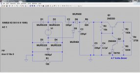
This is something different but could work. Scale C2 as if it were a watt-less dropper. Voltage across C1 is your main HT. Voltage across C3 is the negative bias voltage. Use an resistor/zener stabiliser.
Ignore the rest of the circuit 🙂
This is something different but could work. Scale C2 as if it were a watt-less dropper. Voltage across C1 is your main HT. Voltage across C3 is the negative bias voltage. Use an resistor/zener stabiliser.
Ignore the rest of the circuit 🙂
Attachments
I understand that, but at best any bias supply derived from the HV supply is going to be a reliability risk, and multiplying from lower voltages while possible has its risks, and may result in other performance compromises.
If you are hell bent for leather to do this capacitor couple another bridge across the HV secondary and use that - fine tune the cap values for the required voltage at your load current and make sure you use extremely rugged caps here. (I've done this and had multiple cap failures - ended up with 9 x 0.22uF caps in 3 x 3 series parallel with a small series resistance and that has survived 14yrs so far. Half wave rectification of bias in my case) Ground the positive terminal of the bridge, take output off of the negative terminal. Put a fuse on both sides of the secondary if you do this - use appropriate HV fuse.
IMHO the bias supply needs to be at least as reliable as the HV supply if not more so to protect your output tubes.
If the CT is going to be connected to ground, then you can connect a diode to the 50 v winding, and you have your negative bias...or am i missing something ???
The 50 volt (Violet) tap is a bias tap.
If the CT is grounded, you can connect the violet wire to a diode to produce a negative voltage for biasing your output tubes.
If the CT is grounded, you can connect the violet wire to a diode to produce a negative voltage for biasing your output tubes.
If the CT is going to be connected to ground, then you can connect a diode to the 50 v winding, and you have your negative bias...or am i missing something ???
Uhm ... 😀
Audiolicious said:Which obviously means I can't hook the CT (center tap) to GND and subsequently also can't use the 50V bias voltage winding.
Maybe you can use the CT terminal ,connect a diode in series with a resistor ,and a 5watt zenner to ground and you have your negative bias voltage ( you only need a few milliamps)
Here's what I was thinking could work? Although the output voltage is a tad on the high side, even with a 10mA load on it.
An externally hosted image should be here but it was not working when we last tested it.
Crown did something similar on some of their amplifiers.
I had completely forgotten about that method.
It does work. It won't deliver much current but for bias purposes, you don't need much current.
Perhaps you have solved the problem.
I had completely forgotten about that method.
It does work. It won't deliver much current but for bias purposes, you don't need much current.
Perhaps you have solved the problem.
It is essentially what I did in the amplifier I referenced. This is a half wave implementation of what I posted earlier. Do add a small series resistor to limit line transient induced currents in the cap. You can use the reactance of the capacitor to drop the voltage down into the target region you require, the losses are low unlike resistive dropping.. (Reduce the value of the 10uF cap)
As an aside I don't think the 1kV piv rating of the UF4007 is high enough for the voltages you intend to run the main bridge rectifier at.
As an aside I don't think the 1kV piv rating of the UF4007 is high enough for the voltages you intend to run the main bridge rectifier at.
Here's what I was thinking could work? Although the output voltage is a tad on the high side, even with a 10mA load on it.
An externally hosted image should be here but it was not working when we last tested it.
It is essentially what I did in the amplifier I referenced. This is a half wave implementation of what I posted earlier.
It is indeed, thanks for the suggestion.
As an aside I don't think the 1kV piv rating of the UF4007 is high enough for the voltages you intend to run the main bridge rectifier at.
You're absolutely correct, I was merely running a quick simulation to model the power supply. I actually built it up last evening, using two UF4007s in series, for a total of 8, as I was already looking at the voltage across the diodes in the simulation getting awfully close for comfort.
The capacitor scheme works, but is rather sensitive to capacitor value. After I was content with the ripple voltage and finally arrived at the correct negative voltage I built something the size of a small ~5VA transformer, so I guess it was a fun exercise, but I'll be using that instead.
Thanks for the insightful replies gentlemen, it is appreciated!
Last edited:
Hallo. Sorry resurected this old thread but I.m in similar position using a Hammond power tranny with a 50v tap from ht sec winding. I need more. some into 70v area. A voltage doubler seems to be a decent solution I think but You.re talking about some risk....can You enlight me what potential risk are You talking about. Please?
In same time there are recomandations to use a separate transformer for bias supply. I also have my reserve regards using a stable voltage for bias whilst plate voltage supply will vary in dynamic condition. except the case you using a regulate ht supply or a well oversized one. Relative to that have an other question to experts: How imperative consider the bias voltage supply need to precise track the ht plate voltage variation into dynamic condition.please?
Thank you.
Catalin
Last edited:
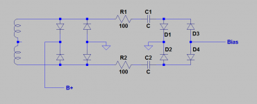
Do you really need to use a bridge rectifier for the positive supply? You can get your bias quite happily from the 50V tapping if you ground the HV winding's centre-tap. You have to then use a full-wave rectifier system i.e. just two diodes at each end of the HV secondary and join the cathodes for your DC output (to filter caps etc). You will have exactly the same efficiency and voltage output for your B+ with no need to go to separate bias transformer or other make-do arrangements. BTW, never regulate bias - otherwise it won't track with changes in plate and screen voltage caused by mains voltage variation and certain other influences.
Kevinkr - I don't think your circuit will work. Consider for a moment that the voltage at the top of the secondary winding is negative. Due to the presence of the reversed diode in the B+ diode bridge, the voltage on that line will be .6V, making the rest of the circuit non-operative.
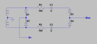
Remove the negative-going diodes in the first bridge and the positive diodes in the bias bridge and ground the secondary centre tap. You now have positive and negative full-wave rectifiers off the secondary.
But why would you do it this way? By grounding the centre-tap and with D1, D2 in a full-wave circuit, he can just use the Hammond 50V tap and a half-wave rectifier for the bias -V.
Attachments
- Home
- Amplifiers
- Tubes / Valves
- Generate a negative bias voltage?