I loved the red, my wife did too. We liked it so much I painted my last pair of speakers red.
I loved the red, my wife did too. We liked it so much I painted my last pair of speakers red.
Great minds and all that.....
Zanders Sub pictures by pothaudio - Photobucket
Any design guidelines on how big to make the radius at the mouth? I imagine many people just go for the biggest practical rounder on their router, but what would you do acoustically if you could machine anything?
Any design guidelines on how big to make the radius at the mouth? I imagine many people just go for the biggest practical rounder on their router, but what would you do acoustically if you could machine anything?
My radi are much larger than anything that you can do on a router - more like 4 inches.
My radi are much larger than anything that you can do on a router - more like 4 inches.
If someone is roughing waveguides, this can be emulated fairly well with elbow grease and a curved hand, (and some sandpaper). Precision isn't important for this roundover, just general smoothness and soft transition to the 'front plane'.
Have you tried putting the same thickness of foam in front of a direct radiating driver?😀I doubt it would give the same effect as when used in the waveguide.🙄 (
Why would you expect it to?
There are no walls for the HOM's to reflect from and give them a longer path lengths.
Why would you expect it to?
There are no walls for the HOM's to reflect from and give them a longer path lengths.
Not to mention the differences in energy intensity.
There are lots of horns/guides, using direct radiating drivers commercially available.Why would you expect it to?
There are no walls for the HOM's to reflect from and give them a longer path lengths.
There are lots of horns/guides, using direct radiating drivers commercially available.
Then they would benefit from the use of foam.
There are lots of horns/guides, using direct radiating drivers commercially available.
I am currently using a shallow waveguide in the car, with a direct radiator. I've definitely noticed an increase in HOMs over the previous design. The previous setup used a BMS compression driver, an elliptical oblate spheroidal waveguide, and reticulated foam.
Then again, the previous setup costs 10x as much.
You get what you pay for, etc etc
If you want to reduce 2nd harmonic distortion, reverse the basket and the polarity of one of the drivers. It makes a measurable and audible difference.
I'm geting close to understanding why aside from the price issue. It's interesting nobody addressed this in technical detail before.I am currently using a shallow waveguide in the car, with a direct radiator. I've definitely noticed an increase in HOMs over the previous design. The previous setup used a BMS compression driver, an elliptical oblate spheroidal waveguide, and reticulated foam.
Then again, the previous setup costs 10x as much.
You get what you pay for, etc etc
What he said ...
4" wide 90deg conical with 1" dome tweeter. They are harsh at higher volumes without the foam. This would seem to indicate HOM's
the foam tames this alot.
but these were built from cheap cast off parts and too much time on my part.
again, what you pay for...
I am currently using a shallow waveguide in the car, with a direct radiator. I've definitely noticed an increase in HOMs over the previous design. The previous setup used a BMS compression driver, an elliptical oblate spheroidal waveguide, and reticulated foam.
Then again, the previous setup costs 10x as much.
You get what you pay for, etc etc
4" wide 90deg conical with 1" dome tweeter. They are harsh at higher volumes without the foam. This would seem to indicate HOM's
the foam tames this alot.
An externally hosted image should be here but it was not working when we last tested it.
but these were built from cheap cast off parts and too much time on my part.
again, what you pay for...
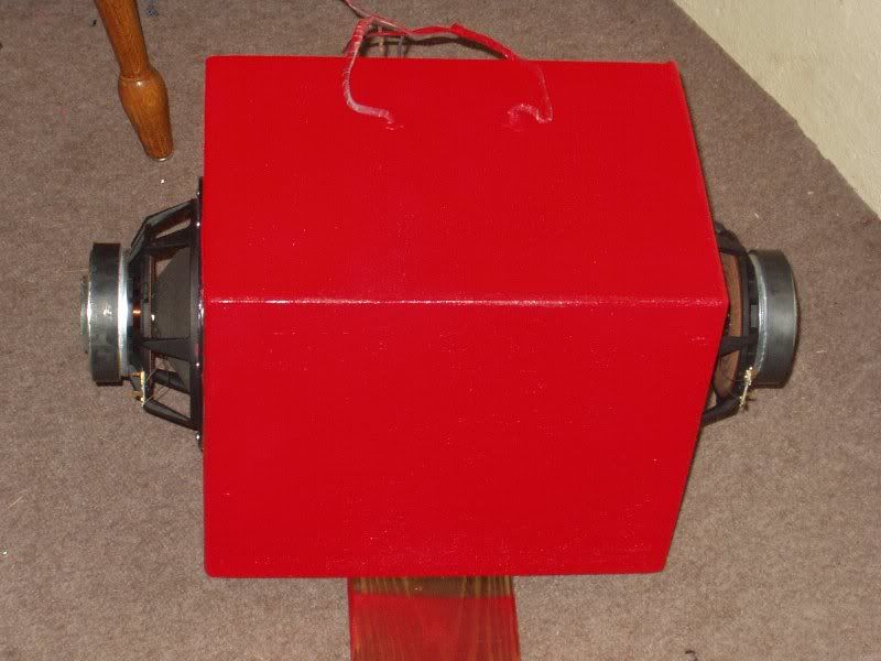
What if that box has four drivers to create an isobaric?If you want to reduce 2nd harmonic distortion, reverse the basket and the polarity of one of the drivers. It makes a measurable and audible difference.
If you want to reduce 2nd harmonic distortion, reverse the basket and the polarity of one of the drivers. It makes a measurable and audible difference.
What if that box has four drivers to create an isobaric?
You nailed it Andrew. There are 2 more drivers, inside. See the flying leads coming out the top?
I have access to CNC, so I can do virtual any freeform shape.My radi are much larger than anything that you can do on a router - more like 4 inches.
Is there any (approximate) formula I can use for predicting the impact of a radius on a waveguide? On the cabinet edge? My intuition is that if diffraction is a change in impedance, it's the dimensions of the edge relative to the source that determine the frequency, and the round over lowers the q? Would it be fair to say that 4" is a sufficient rounder for most purposes, or would it be worthwhile to go even further and make the cabinet more sphere than box?
I have access to CNC, so I can do virtual any freeform shape.
Is there any (approximate) formula I can use for predicting the impact of a radius on a waveguide? On the cabinet edge? My intuition is that if diffraction is a change in impedance, it's the dimensions of the edge relative to the source that determine the frequency, and the round over lowers the q? Would it be fair to say that 4" is a sufficient rounder for most purposes, or would it be worthwhile to go even further and make the cabinet more sphere than box?
These are questions worthy of some research, but from what is known, what you say is basically correct. SPEAK does a rough job of predicting the effect of a roundover on the polar response and this is also discussed in my book.
Hi jason_watkins
There has been some research on round over or chamfer of baffle edges been published in an German DIY magazine – IIRC there is a certain relation to wavelength involved, as one would expect ...
As for round over the mouth of a horn you might get some inspiration from my simus performed on the topic here:
#472
http://www.diyaudio.com/forums/multi-way/140190-jean-michel-lecleach-horns-10.html#post1924924
and from my "bunch 1 through 4" here :
#3299
http://www.diyaudio.com/forums/multi-way/103872-geddes-waveguides-66.html#post1927587
#3300
http://www.diyaudio.com/forums/multi-way/103872-geddes-waveguides-66.html#post1927588
#3301
http://www.diyaudio.com/forums/multi-way/103872-geddes-waveguides-67.html#post1927590
#3302
http://www.diyaudio.com/forums/multi-way/103872-geddes-waveguides-67.html#post1927591
And possibly also what rcw has shown here:
http://www.diyaudio.com/forums/multi-way/140190-jean-michel-lecleach-horns-9.html#post1891820
http://www.diyaudio.com/forums/multi-way/140190-jean-michel-lecleach-horns-9.html#post1897176
http://www.diyaudio.com/forums/multi-way/103872-geddes-waveguides-66.html#post1916842
Bottom line – there already has been *some* investigation lately...
🙂
Michael
Last edited:
Elliptical OSWG parameters:
- throat diameter
- coverage
- mouth diameter
- roundover radius
I did a sketch with 45/90 deg coverage and fixed 5cm roundover keeping the length and mouth diameter constant. Is this correct or make length varied and roundover as in Iwata, JMLC, Ferguson horns?
- throat diameter
- coverage
- mouth diameter
- roundover radius
I did a sketch with 45/90 deg coverage and fixed 5cm roundover keeping the length and mouth diameter constant. Is this correct or make length varied and roundover as in Iwata, JMLC, Ferguson horns?
Attachments
- Home
- Loudspeakers
- Multi-Way
- Geddes on Waveguides