When you say "adding energy". Where do you propose the additional energy is coming from?rcw said:I did a similar post to this but I somehow got it in a topic called "beyond the Ariel"
Any way what I observed was that it is entirely within the bounds of possibility that the author of the university of Adelaide paper came to his conclusions quite independently and did not read the Geddes book, and if he did and took material from it and did not mention it, he is guilty of plagiarism, not an accusation I would make lightly.
It should also be obvious that if the duct wall has an increasing slope the the non parallel wavefronts this produces are constantly adding energy to the evanescent field by scattering, and that these waves will propagate should the local cut off frequency become equal to the evanescent wave frequency.
rcw
Dr. Geddes, I was half joking about the car waveguides. But that being said, I would love to see what you did for cars...I'm more into car stereos than home- spend much more time in the car than in the house.
John, can't wait...can't wait!
John, can't wait...can't wait!
Re: Chapter 6
The acoustic center is changing in that the diffraction wave have a different acoustic center than the undiffracted portion. This is what causes the group delay. Being that there is not a simple single acoustic center its hard to answer your question.
Since Huygens principle and the wave equation are basically the same thing and my work is done with the wave equation then in a sense you are correct. HOMs within the waveguide are created by the diffraction and the mouth reflection, but they can also be created at the throat by a wave mismatch between the source and the waveguide.
soongsc said:Dr. Geddes,
Since Huygen¡¦s principle is mentioned in the book, it seems that based on this, in a traditional horn, the acoustic center is continously changing due to diffraction, and that depending on shape of final wave front, AC could actually be different on-axis versus off-axis. Do I interpret this currectly? If not, could you elaborate a bit more on this?
Is your idea of HOMs due to the horn/guide based mainly on understanding that based on Huygen¡¦s principle, the diffraction reflection is the source of HOMs?
The acoustic center is changing in that the diffraction wave have a different acoustic center than the undiffracted portion. This is what causes the group delay. Being that there is not a simple single acoustic center its hard to answer your question.
Since Huygens principle and the wave equation are basically the same thing and my work is done with the wave equation then in a sense you are correct. HOMs within the waveguide are created by the diffraction and the mouth reflection, but they can also be created at the throat by a wave mismatch between the source and the waveguide.
rcw said:I did a similar post to this but I somehow got it in a topic called "beyond the Ariel"
Any way what I observed was that it is entirely within the bounds of possibility that the author of the university of Adelaide paper came to his conclusions quite independently and did not read the Geddes book, and if he did and took material from it and did not mention it, he is guilty of plagiarism, not an accusation I would make lightly.
It should also be obvious that if the duct wall has an increasing slope the the non parallel wavefronts this produces are constantly adding energy to the evanescent field by scattering, and that these waves will propagate should the local cut off frequency become equal to the evanescent wave frequency.
rcw
Dr. Morgan did read and use my book and says so in his thesis. It is not plagarism to use the work of others in your own work so long as you reference it, whcih he did.
I hope your not going to start with the "scattering" stuff here too. I thought that we put that to rest? Those of you who are confused (as I am when I read "scattering") may want to read the posts over at "Arial".
How would a second woofer above the waveguide affect the vertical polar response? D'appolito alignments are said to be beneficial in this case, but i have some doubts about this.
MaVo said:How would a second woofer above the waveguide affect the vertical polar response? D'appolito alignments are said to be beneficial in this case, but i have some doubts about this.
Something like this?
(Yorkville U215)
Attachments
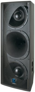
Yes, only that the U215 will probably have a lower crossover point, which should have some influence on the polar response. But thanks for the hint. 🙂
Edit: crossover at 300hz, which is quite different from the summa speakers.
Edit: crossover at 300hz, which is quite different from the summa speakers.
MaVo said:
Edit: crossover at 300hz, which is quite different from the summa speakers.
I take it you will use BMS mid/tweet coax
AT some time it was mentioned that crossing a CD mid that low results in very thin and harsh sound ... could be something else though
No BMS coax, its a unity loudspeaker licensed from Tomas Danley. It uses three 5 inch midranges around the waveguide throat - which is, according to Dr Geddes, quite the HOM producer.
MaVo said:How would a second woofer above the waveguide affect the vertical polar response? D'appolito alignments are said to be beneficial in this case, but i have some doubts about this.
You're right, the MTM arrangement is done to set the null angles. Of couse, crossover frequency and the positions of the drivers are important, as they determine where the null angles will fall.
Here again, I would use a tweeter with vertical coverage approximately equal to the null angle. The nulls mark the edge of useful coverage. Beyond that, sound quality is poor. Within the null angle, summing is coherent. Outside the null angle, it isn't. Large vertical angles only increase floor and ceiling reflections. So in my opinion, there is no good reason for the tweeter horn to direct energy outside the null angle. As much as possible, radiation at large vertical angles should be reduced.
tinitus said:
I take it you will use BMS mid/tweet coax
AT some time it was mentioned that crossing a CD mid that low results in very thin and harsh sound ... could be something else though
The U215 is a Unity horn. Whole different animal than a conventional horn.
MaVo said:No BMS coax, its a unity loudspeaker licensed from Tomas Danley. It uses three 5 inch midranges around the waveguide throat - which is, according to Dr Geddes, quite the HOM producer.
Beyond the issue of high-order modes, reflections bouncing back and forth from wall to wall, I have always wondered about nodes appearing within the pattern of a Unity style horn. I'd like to see a plot of response from a microphone array tightly spaced in the mouth to get an idea of the energy at all places within the mouth.
Tom's idea is clever, essentially to fold the baffle into a conical horn and shift the null angle to try and move them outside the pattern. However, there are two primary nulls, not one. So they still would have to be placed on either side of the flare for both of them to be outside the pattern. I suppose it is possible, certainly that is what Danley strives for in his design.
I just always couldn't help but wonder if nulls fall within the pattern. Of course, having multiple drivers helps, because they can average the sound field if nulls do fall within the pattern, as long as they don't fall in the same place. The firsy Unity horn I ever saw had a huge on-axis spiked dip though, which made me think it was probably a summing cancellation notch. I expect that horn had null angles placing one null far off-axis and the other directly on the forward axis, causing the notch.
FrankWW said:See beyond ariel thread post 4131 and 4147
http://www.diyaudio.com/forums/showthread.php?postid=1552329#post1552329
Everyone reading this thread should go and download that paper - there's a lot of food for thought in there.
There's one theme which I find very intriguing. It's hard for me to describe it broadly, so if anyone wants clarification, please let me know. The theme I see in the paper is that the CURVE of the horn isn't critically important. Here on the forums I see a lot of people debating CURVEs, when my experience and my study of this subject has taught me that there are many elements to a horn (and a waveguide) which are more important that the CURVE.
For instance, you'll notice that the area of the various horns in the paper is almost identical, and they all share a common theme. The slope of each curve changes veeeeeery gradually. This is in stark contrast to the diffraction horns which are so common.
I've posted a couple of pics from the doc, so you can see what I'm talking about. Note that the throat size and the coverage angle are different, so the geometry is different. But the theme is the same - a VERY gentle change in angle travelling down the length of the horn.
Naturally Geddes has mentioned something along those lines in this very thread; it's certainly worth contemplation.


Notice the dip in beamwidth at LF just before the rise as pattern control is lost. This is the behavior of single slit diffraction, a result of the dimensions of the mouth.
Re: Re: Chapter 6
Based on analysis what would be the order of magnitude of HOMs generated by say a 0.1mm mismatch at the throat of your design?
So since the acoustic centers are shifting as the wave travels done the guide/horn, that means the shape of the wave front is continuously changing, and thus the wave length would actually be changing, wouldn't it? So if we measure a single frequency generated from the driver, the measured frequency might actually be different from the original signal. Wouldn't it?gedlee said:
The acoustic center is changing in that the diffraction wave have a different acoustic center than the undiffracted portion. This is what causes the group delay. Being that there is not a simple single acoustic center its hard to answer your question.
Since Huygens principle and the wave equation are basically the same thing and my work is done with the wave equation then in a sense you are correct. HOMs within the waveguide are created by the diffraction and the mouth reflection, but they can also be created at the throat by a wave mismatch between the source and the waveguide.
Based on analysis what would be the order of magnitude of HOMs generated by say a 0.1mm mismatch at the throat of your design?
It seems the throat design is much more critical most people may think, and actually has effect on off axis response. Very interesting.Patrick Bateman said:
Everyone reading this thread should go and download that paper - there's a lot of food for thought in there.
There's one theme which I find very intriguing. It's hard for me to describe it broadly, so if anyone wants clarification, please let me know. The theme I see in the paper is that the CURVE of the horn isn't critically important. Here on the forums I see a lot of people debating CURVEs, when my experience and my study of this subject has taught me that there are many elements to a horn (and a waveguide) which are more important that the CURVE.
For instance, you'll notice that the area of the various horns in the paper is almost identical, and they all share a common theme. The slope of each curve changes veeeeeery gradually. This is in stark contrast to the diffraction horns which are so common.
I've posted a couple of pics from the doc, so you can see what I'm talking about. Note that the throat size and the coverage angle are different, so the geometry is different. But the theme is the same - a VERY gentle change in angle travelling down the length of the horn.
Naturally Geddes has mentioned something along those lines in this very thread; it's certainly worth contemplation.
Patrick Bateman said:
Everyone reading this thread should go and download that paper - there's a lot of food for thought in there.
This thesis was really quite excellent, but after contemplating it awhile there are some holes.
For instance he optimized arround a coverage angle. This could easily cause problem with the smoothness of the response within these angles since this is not a criteria in the optimization algorithm. I would be interested in seeing polar maps for these devices not just coverage angle versus frequency. Some of the smoother coverage angle versus frequency came with some rather sharp edge curves. This would increase the edge diffraction not decrease it. But this may help to control the pattern but cause irregularities within the coverage zone.
As I said before after I read this thesis, nothing in it would entice me to change the way I do anything now. It basically confimed what I am already doing.
Re: Re: Re: Chapter 6
No, this is not correct. The frequency does not change, and the wavelength is constant as it propagates, although there is a phase shift between the pressure and the velocity of the wavefront as it propagates, which means that looking at one or the other the wavelength might appear to change, but when looking at the wavelength of the energy it remains constant.
soongsc said:
So since the acoustic centers are shifting as the wave travels done the guide/horn, that means the shape of the wave front is continuously changing, and thus the wave length would actually be changing, wouldn't it? So if we measure a single frequency generated from the driver, the measured frequency might actually be different from the original signal. Wouldn't it?
Based on analysis what would be the order of magnitude of HOMs generated by say a 0.1mm mismatch at the throat of your design?
No, this is not correct. The frequency does not change, and the wavelength is constant as it propagates, although there is a phase shift between the pressure and the velocity of the wavefront as it propagates, which means that looking at one or the other the wavelength might appear to change, but when looking at the wavelength of the energy it remains constant.
To answer Soongs question, a spherical wave has a complex impedance that has both a real and imaginary part, and the imaginary part can store energy just as capacitors and inductors can.
The real part of the impedance can be looked at as a resistor that bleeds off some of the energy in the imaginary part, the exponential decay known as evanescent waves results, if the local geometry does not allow a wave of that mode and frequency to propagate.
The point is that the frequency does not change but the shape of the wavefront does if the wall is flaring and the change in shape adds modal components.
What also happens is that at a certain frequency the real part of the impedance dominates and the imaginary part becomes very small, and at this point the wavefront can be said to "leave the wall", this is because the acoustic field has become predominantly a potential field that has no curvature.
rcw
“Beyond the issue of high-order modes, reflections bouncing back and forth from wall to wall, I have always wondered about nodes appearing within the pattern of a Unity style horn. I'd like to see a plot of response from a microphone array tightly spaced in the mouth to get an idea of the energy at all places within the mouth.
Tom's idea is clever, essentially to fold the baffle into a conical horn and shift the null angle to try and move them outside the pattern. However, there are two primary nulls, not one. So they still would have to be placed on either side of the flare for both of them to be outside the pattern. I suppose it is possible, certainly that is what Danley strives for in his design.”
Wayne, not sure what “microphone array tightly spaced in the mouth” will tell you.
On the other hand, for the current version the Synergy horn, “where the sound goes” after leaving the speaker, over the surface of a sphere is known to a degree that is very unusual in the hifi world and from measurements taken by a third party.
Download the CLF file for an SH-50, rotate the spherical balloon, look at the polars, there are no crossover notches at all, the drivers are too close together at crossover to interfere like that. Look at 315 and 1Khz for instance.
Think about two woofers, you place them ¼ wl or less apart, they feel each other, they add coherently, they radiate as a point source, have no directivity.
It is the same here, where ever there is a crossover, the spacing between ranges is less than ¼ wl and the electrical phase is appropriate, they combine into one source and drive the horn from a dimension where it is “acoustically small” so the horn alone defines the pattern angle and one set ‘feels” the other.
Think about the midrange drivers, at 1000Hz, there are eight entry holes (sources in the horn) and the horn dimension is about 2 3/4 inches across. With all 8 sources in phase and this dimension, there is no opportunity for them to produce hom’s.
The first unity horn you saw was a DIY version, it had a nice blended throat, while that looked great, "seemed right", that combined with the mid hole detail, caused a “black spot” at 4KHz exactly on axis about 10dB deep. That was from an internal reflection and could be reduced to about 3 dB by placing 4 triangles of absorbing foam near the mouth where those modes bounced off..
Production horns didn’t have that, all went directly into a conical shape, were driven with a driver that already produced a diverging wave front when the sound entered the horn.
There has also been 8 years of development since.
Frankly, I don’t see a mechanism to produce higher order modes in a simple conical horn when the horn is driven “in phase” from a dimension that is say ¼ wl or less across.
I would guess for a one inch driver, regardless of how wrong it is for say a 50 degree conical horn, probably wouldn’t produce higher order modes below say 8KHz.
A 2 inch 80’s Pro driver on a wide horn, now that typically is a can of HOM worms.
I told Earl I would record pink noise for him on a polar table measure of an SH-50 and he can plot out what ever it says. Soon I have to do a bunch of measurements outdoors and I’ll do that then (requires fogging the yard for mosquitoes, a bumper crop this year).
I don’t see much energy being radiated out of pattern (where higher modes go) in the measured polar’s though.
Keep in mind that while people talk about a plane wave coming out of the driver, that usually isn’t what it is up high, some drivers actually produce a converging wavefront which produces HOM’s high up beginning inside the driver.
On the other hand what I have done is look for drivers which already have a divergent curved wavefront as they exit. Then to a degree, the faster you can transition to the final wall angle, the smaller the horn dimension still is, the higher any possible issues go.
The general idea it seems to me is that for a conical horn, your horn path must produce a wave front shape suitably curved for the desired “spherical segment” conical horn, way before your acoustic dimension affects / begins to govern directivity.
This is akin to bending around a corner such as in this device, 20KHz will go around a corner is the differential distance is small as in this; “view breakaway”
http://www.vtcproaudio.com/technology/paraline.html
A Change in direction after the acoustic dimension is governing the directivity, causes problems, except in Earl’s curious horn, which I would consider an exception, it (to me) has a precisely related, acceptably small rate of change of direction per this acoustic governing dimension. It is geometry I wouldn’t have thought of and I don’t see how he thought of that based on the math so my hat is off to Earl.
Wayne, you have always been a verbal skeptic yet so far as I am aware have never heard anything we make.
If your ever back in Chicago again, I would invite you to finally hear what my speakers sound like yourself by going to the IMAX Movie theater at Navy Pier, the first installation has just opened after re-fitting with our SH-96's and TH-50 subs.
Keep in mind its a big room.
We don’t make home speakers but it is actually pretty hard, even harder in some ways than in the home I think, to make good sound in large spaces. My interest in doing it in large spaces is certainly no less than doing it in my home however.
Tom Danley
- Home
- Loudspeakers
- Multi-Way
- Geddes on Waveguides