Thanks Frank - that had completely slipped my mind (which is the second thing to go with old age!)
Please note that this is a 2-stage solution, not purely PS. The first stage is an Elliptic Cylinder section and the second stage is truly a PS.
Please note that this is a 2-stage solution, not purely PS. The first stage is an Elliptic Cylinder section and the second stage is truly a PS.
Last edited:
I was looking at some gear on eBay today and noticed that Clair Brothers has a monitor that looks a lot like a Summa now.
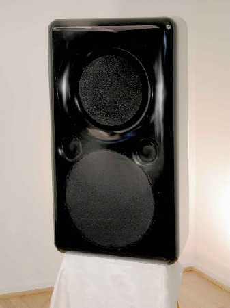
Here's a Summa. It's a two way with a B&C compression driver and a 15" woofer.
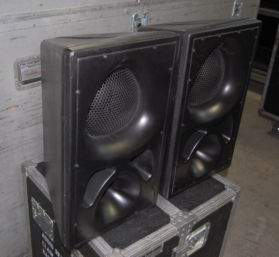
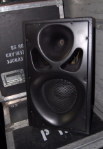
Here's the Clair P110. It's a two way with a BMS compression driver and a 10" woofer.
Here's a Summa. It's a two way with a B&C compression driver and a 15" woofer.
Here's the Clair P110. It's a two way with a BMS compression driver and a 10" woofer.
Passing resemblance, but the P110 semi-triangular horn does not follow the oblate spheroid expansion pattern, it appears to be continually expanding, which would result in a narrowing HF pattern.I was looking at some gear on eBay today and noticed that Clair Brothers has a monitor that looks a lot like a Summa now.
Here's the Clair P110. It's a two way with a BMS compression driver and a 10" woofer.
The HF dispersion pattern probably is consistent with the narrow cabinet wall angles.
Attachments
I was looking at the Gedlee speakers on Earls site, but there no audio coming out of my QSC K's. So many sites do not have audio. Oddly speaker sites usually do not.
What is the price of finished built Abbey today? Or what did the cost at the end, if they aren't sold anymore.
The Abbey is no longer available. I believe the last price was $1800 for an assembled, finished and tested speaker.
Im looking to build an oblate spheriodal waveguide from plaster. Im trying to make the throat to match the 6degree exit angle of my B&C de250 compression driver. Josh K mentions that he adapted his spreadsheet to include the cd exit angle. Only i can't find this version of the spreadsheet. Would someone be willing to send it to me / post it here?
Exit from compression driver = shape A
Throat of horn = shape B
Smoothest / least distortion = gradual and physically economical transition from shape a to shape b, no extranious pedantic verbage or obscure patents needed. That is all there is to it, period 🙂
Throat of horn = shape B
Smoothest / least distortion = gradual and physically economical transition from shape a to shape b, no extranious pedantic verbage or obscure patents needed. That is all there is to it, period 🙂
Last edited:
See Post ...
http://www.diyaudio.com/forums/mult...n-compression-driver-os-horn.html#post2327385
for the math.
Regards,
WHG
Im looking to build an oblate spheriodal waveguide from plaster. Im trying to make the throat to match the 6degree exit angle of my B&C de250 compression driver. Josh K mentions that he adapted his spreadsheet to include the cd exit angle. Only i can't find this version of the spreadsheet. Would someone be willing to send it to me / post it here?
http://www.diyaudio.com/forums/mult...n-compression-driver-os-horn.html#post2327385
for the math.
Regards,
WHG
Pete,Exit from compression driver = shape A
Throat of horn = shape B
Smoothest / least distortion = gradual and physically economical transition from shape a to shape b, no extranious pedantic verbage or obscure patents needed. That is all there is to it, period 🙂
Yes, that's "all there is too it" if one does not mind high frequency pattern narrowing, which the OS expansion specifically avoids up to around 12 kHz.
BTW, spell check is your friend when you use big wordz ;^).
Cheers,
Art
Thanks for the replies. Im feeling a bit dumb when i look at those lists of equations. Im starting to remember why i quit electrical engineering 😀
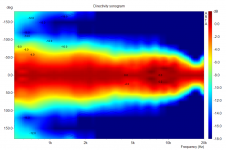
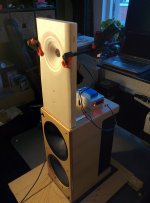
I used the spreadsheet provided by Josh K to make the attached waveguide profile (the enormous exit radius is on purpose). Im trying to mimic a waveguide from a test baffle i did some tests with, which works quite well apart from some diffraction at 10KHz and narrowing above 12KHz. At least the diffraction at 10KHz is probably caused by non-optimal matching between waveguide exit and horn throat, as each iteration of adapter for providing a smooth transition improved the 10KHz behaviour (see attached polar).
So now im looking to improve the accuracy of the throat. The aforementioned spreadsheet by Josh K is perfect in drawing the profile in the right dimensions, only i can't change the cd exit angle. I have one version in which you can enter the exit angle, only it doesn't seem to work. Is there a working version around 🙂 ?
Attachments


Hi Jag768Thanks for the replies. Im feeling a bit dumb when i look at those lists of equations. Im starting to remember why i quit electrical engineering 😀
I used the spreadsheet provided by Josh K to make the attached waveguide profile (the enormous exit radius is on purpose). Im trying to mimic a waveguide from a test baffle i did some tests with, which works quite well apart from some diffraction at 10KHz and narrowing above 12KHz. At least the diffraction at 10KHz is probably caused by non-optimal matching between waveguide exit and horn throat, as each iteration of adapter for providing a smooth transition improved the 10KHz behaviour (see attached polar).
So now im looking to improve the accuracy of the throat. The aforementioned spreadsheet by Josh K is perfect in drawing the profile in the right dimensions, only i can't change the cd exit angle. I have one version in which you can enter the exit angle, only it doesn't seem to work. Is there a working version around 🙂 ?
May this can help for calculating OS-WG horn profile:
Ro =driver throat radius
To = driver mouth exit angle
Te =coverage angle (form axis)
Then
ro = Ro*sqrt( 1 - [tan(To)/tan(Te)]^2)
Xo = Ro/tan(Te)*tan(To)/tan(Te)
y(x) = ro*sqrt( 1+ {[(x+Xo)/ro]*tan(Te)}^2), x={0……}
Regards
Ivica
Nota Bene
When you set the parameters of the 1st derivative and set the coverage angle as well, the horn profile dimensions will change to meet this criteria.
Alternatively you must design a transition segment that continues the flare of compression driver until a some distant diameter a tangent point is reached with an existing horn profile. Ideally, use a compression driver designed to exit into the apex (at 0°) of the hyperbola that forms an OS horn profile.
N.B., EE is a 'cake-walk' compared to AE.
In this thread we are only dealing with 2nd. year high-school algebra where Calculus is first introduced.
Regards,
WHG
Thanks for the replies. Im feeling a bit dumb when i look at those lists of equations. Im starting to remember why i quit electrical engineering 😀
I used the spreadsheet provided by Josh K to make the attached waveguide profile (the enormous exit radius is on purpose). Im trying to mimic a waveguide from a test baffle i did some tests with, which works quite well apart from some diffraction at 10KHz and narrowing above 12KHz. At least the diffraction at 10KHz is probably caused by non-optimal matching between waveguide exit and horn throat, as each iteration of adapter for providing a smooth transition improved the 10KHz behaviour (see attached polar).
So now im looking to improve the accuracy of the throat. The aforementioned spreadsheet by Josh K is perfect in drawing the profile in the right dimensions, only i can't change the cd exit angle. I have one version in which you can enter the exit angle, only it doesn't seem to work. Is there a working version around 🙂 ?
When you set the parameters of the 1st derivative and set the coverage angle as well, the horn profile dimensions will change to meet this criteria.
Alternatively you must design a transition segment that continues the flare of compression driver until a some distant diameter a tangent point is reached with an existing horn profile. Ideally, use a compression driver designed to exit into the apex (at 0°) of the hyperbola that forms an OS horn profile.
N.B., EE is a 'cake-walk' compared to AE.
In this thread we are only dealing with 2nd. year high-school algebra where Calculus is first introduced.
Regards,
WHG
Last edited:
Ideally, use a compression driver designed to exit into the apex (at 0°) of the hyperbola that forms an OS horn profile.
Unfortunately - to my knowledge - none of these exist.
Better would be to have the OS flare continue through the phase plug right down to the diaphragm. I had a patent on this at one time - interchangeable phase plugs for different waveguide configurations.
Concur
Earl,
Totally agree with you on this, and a reverse flare could be used as the apex is approached from the negative side of the hyperbola. However the JBL 2447 & 2451 CD's come close to meeting the mission; and by now, there may be others as well. For those unaware, the attached Tech-Note [1] provides some design details.
Regards,
Bill
Reference [1]
Unfortunately - to my knowledge - none of these exist.
Better would be to have the OS flare continue through the phase plug right down to the diaphragm. I had a patent on this at one time - interchangeable phase plugs for different waveguide configurations.
Earl,
Totally agree with you on this, and a reverse flare could be used as the apex is approached from the negative side of the hyperbola. However the JBL 2447 & 2451 CD's come close to meeting the mission; and by now, there may be others as well. For those unaware, the attached Tech-Note [1] provides some design details.
Regards,
Bill
Reference [1]
Attachments
Last edited:
Im looking to build an oblate spheriodal waveguide from plaster. Im trying to make the throat to match the 6degree exit angle of my B&C de250 compression driver. Josh K mentions that he adapted his spreadsheet to include the cd exit angle. Only i can't find this version of the spreadsheet. Would someone be willing to send it to me / post it here?
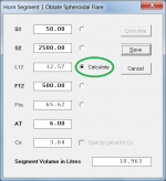
The Hornresp Horn Segment Wizard tool will give you what you want - just select the Calculate option that best suits your needs.
For example...
In Attachment 1:
Specified:
Throat area S1 = 50 cm2
Mouth Area S2 = 2500 cm2
Cutoff frequency F12 = 500 Hz
Throat entry half-angle AT = 6 degrees *
* Change AT to 3 degrees if the "6 degree exit angle" referred to is the total included angle, not the half-angle.
Calculated:
Waveguide axial length L12 = 12.57 cm
Mouth flare tangent angle Fta = 65.62 degrees
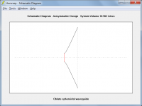
Attachment 2 shows the schematic diagram for the specified waveguide. Dimensional data can be exported for construction purposes.
Attachments
Last edited:
As I have remembered OSWG are of CD horn type, so mouth flare curve is not specified explicitly given but E.G. has suggested to be of semicircular flare whose radius is about Lamda/4, where Lamda corresponds to lowest usable frequencyHi Jag768
May this can help for calculating OS-WG horn profile:
Ro =driver throat radius
To = driver mouth exit angle
Te =coverage angle (form axis)
Then
ro = Ro*sqrt( 1 - [tan(To)/tan(Te)]^2)
Xo = Ro/tan(Te)*tan(To)/tan(Te)
y(x) = ro*sqrt( 1+ {[(x+Xo)/ro]*tan(Te)}^2), x={0……}
Regards
Ivica
Regards
Ivica
As I have remembered OSWG are of CD horn type, so mouth flare curve is not specified explicitly given but E.G. has suggested to be of semicircular flare whose radius is about Lamda/4, where Lamda corresponds to lowest usable frequency
Regards
Ivica
Mouth flare is never part of any horn/waveguide theory, they all deal with devices of infinite extent. The role of the mouth flare is covered in my book. Basically the larger the radius the better, but beyond a certain point it becomes impractical and less effective.
- Home
- Loudspeakers
- Multi-Way
- Geddes on Waveguides