gedlee said:
..... The subject of difraction is very complex. I could give you many references on it, but I'd need to know the level of math that you are comfortable with. At a low level of math there is not going to be much since the topic is not an easy one.
Let me give you some "rules of thumb"
1) the dffraction is proportional to sounce intensity - it is linear
2) The sharper the edge the more diffraction. It is actually proportional to the 2nd derivative of the surface. A "knife edge" therefor is a worst case.
3) The higher the frequency for a given edge the greater the diffraction intensity.
Math skills? 😀 Long time passed since technical university. I can understand what is integer, derivative what does it mean but that is all. IMHO low level.
I wanted to quatify distinction between phantom source intensity for rounded edges of different diameters. Just out of curiosity.
noah katz said:Ah, of course - the original statement "the diffraction is proportional to source intensity - it is linear" is referring to the SPL of the diffracted wave, not how much it is diffracted (bent).
Bingo
Seeing your misunderstanding, I should have said: "The diffraction FIELD INTENSITY is proportional to source intensity - it is linear"
catapult said:"If you can't explain it simply, you don't understand it well enough."
Albert Einstein
"I thought my 'simple' explaination was suitable."
Earl Geddes
But anyways, I've never liked that quote as I don't believe that it's actually true. There is no simple way to picture or explain General Relativity (for example). You can make it "simple", but I can pretty much guarantee that it will be misunderstood.
They can behave very diffently with as little as 1mm difference in the contour. The closer to the thoat, the more sensitive it is to tolerances.Patrick Bateman said:
Speaking of trade secrets, I did some polar measurements of an OS waveguide and an XT1086 that I cloned, and was surprised that there was such a difference, considering how similar the curves are.
Then again, I did the measurements in my car, so ymmv.
But it's still curious that two similar waveguides could behave so differently.
From the look of things....
Some of the work you've done is pretty rough. I'd not try to draw conclusions about horn geometry from them until I had some more process refinement.
Some of the work you've done is pretty rough. I'd not try to draw conclusions about horn geometry from them until I had some more process refinement.
soongsc said:
The closer to the thoat, the more sensitive it is to tolerances.
That we learned from the beginning of this 😉
If you want to make a 100% exact copy of your simulated waveguide, its only possible with CNC machining
Impossible with molding
Or it will be exstremely expencive
But you could have at least a throath adapter machined
I believe the hard core guys do that
Group buy ? 😀
Dr. Geddes,
Would you please give your input on this: http://www.diyaudio.com/forums/showthread.php?postid=1855108#post1855108
Since you peer reviewed the article, I presume the term "inner membrane" is unambiguous to you?
Thanks,
_-_-bear
PS. If I had used the term "inner membrane" I would likely have found a situation where there was perhaps an "outer membrane"? Or, "intermediate membrane"... etc. Otherwise why not just "membrane"? Or if there is a function to the membrane, then "driven membrane" or "mechanical membrane", etc... Thus my confusion stems...
Patrick Bateman said:
The strange thing is that the XT1086 changes coverage angles slower than the OS curve. The coverage angle in an OS waveguide changes from six degrees to ninety degrees in the span of 1/2". The XT1086 changes it's coverage angle very VERY slowly.
I would think that this wouldn't be a bad thing, but the polars are inferior.
Having said that, the data is a bit suspect, due to where it was measured.
I'll take a picture of an elliptical OS waveguide and the XT1086 and post it, it will make more sense then.
I'll state the obvious - if the shape (expansion) is different then no matter how it looks, it is not an OS waveguide.
Since you are doing a mold, you might modify the molded part to meet the OS expansion specs more closely?
_-_-bear
I think it is possible to get consistent results with molding once the mold shape is properly designed. The thoat really needs to be designed for a specific driver.tinitus said:
That we learned from the beginning of this 😉
If you want to make a 100% exact copy of your simulated waveguide, its only possible with CNC machining
Impossible with molding
Or it will be exstremely expencive
But you could have at least a throath adapter machined
I believe the hard core guys do that
Group buy ? 😀
bear said:Dr. Geddes,
Would you please give your input on this: http://www.diyaudio.com/forums/showthread.php?postid=1855108#post1855108
Since you peer reviewed the article, I presume the term "inner membrane" is unambiguous to you?
Thanks,
_-_-bear
PS. If I had used the term "inner membrane" I would likely have found a situation where there was perhaps an "outer membrane"? Or, "intermediate membrane"... etc. Otherwise why not just "membrane"? Or if there is a function to the membrane, then "driven membrane" or "mechanical membrane", etc... Thus my confusion stems...
Hi Bear
I don't remember that level of detail, but I would have to assme that he meant the diaphragm located within the compression driver. I can't see it meaning anything else despite the ambiguity that the wording implies. Remember that English was not his first language.
badman said:I've emailed JBL, hopefully I'll hear back from them.
Unrelated- an elliptical OS is just a 'squashed' conical, is that correct? My particular casting method actually makes an elliptical every bit as easy as a conical. I have to retrofit the mouth roundouts on either geometry using styrofoam forms and TLC anyway.
Per an engineer I talked to @ JBL, the throat of the 2426 has no horn flare (with the 1" throat, with larger throats, they have flares).
"Per an engineer I talked to @ JBL, the throat of the 2426 has no horn flare"
Hello badman
That seems odd?? A 2420 sure does. Look at the crosssections in the L300 brochure as an example. I would think the only drivers that don't have a flare are the newer 1.5" throatless drivers.
If you take a small flashlight like a AA Maglite and shine it through the screen of a 2426 it sure looks tapered to me. I just did it. Take a look and see what you think.
Rob 🙂
Robh3606 said:"Per an engineer I talked to @ JBL, the throat of the 2426 has no horn flare"
Hello badman
That seems odd?? A 2420 sure does. Look at the crosssections in the L300 brochure as an example. I would think the only drivers that don't have a flare are the newer 1.5" throatless drivers.
If you take a small flashlight like a AA Maglite and shine it through the screen of a 2426 it sure looks tapered to me. I just did it. Take a look and see what you think.
Rob 🙂
Hi Rob:
Yes, indeed, it seems odd. When I get closer to completion of the 'main' part of the waveguide, I'll pull the drivers and confirm. For now, the guides are molded to taper to a very shallow angle, which should be fairly easy to convert to whatever I need.
Thanks for responding, I should have mentioned that it was not truly confirmed, to prevent people from assuming the engineer was accurate. He wasn't, shall we say, brilliant......
Hello,
Regards, Timo
Please look into "Horndesign und Hornoptimierung mittels BEM" at page 7. As I understand, two positions were meant: the junction between driver and horn and the junction between throat and the horn itself. The throat was to be modified further for impedance matching and the horn for directivity in _this_ case. So the "new membrane" was located at the diffraction slot for the directivity improvement.gedlee said:I don't remember that level of detail, but I would have to assme that he meant the diaphragm located within the compression driver.
Regards, Timo
tiki said:Hello,
Please look into "Horndesign und Hornoptimierung mittels BEM" at page 7. As I understand, two positions were meant: the junction between driver and horn and the junction between throat and the horn itself. The throat was to be modified further for impedance matching and the horn for directivity in _this_ case. So the "new membrane" was located at the diffraction slot for the directivity improvement.
Regards, Timo
Sorry... what paper? which author??
I was referring to the Makarski paper...
You are saying then a "virtual" membrane??
_-_-bear
bear said:
I'll state the obvious - if the shape (expansion) is different then no matter how it looks, it is not an OS waveguide.
Since you are doing a mold, you might modify the molded part to meet the OS expansion specs more closely?
_-_-bear
Absolutely. The thing that's a bummer is that I'll bet a number of people have bought the XT1086 and assumed it's a substitute for an OS waveguide, based on how the mouth looks. But the throat diverges from OS by quite a bit.
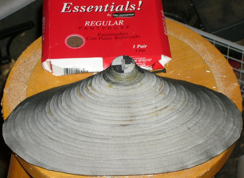
This is my elliptical OS waveguide mold. Sorry I don't have a better pic - this is before I applied glass and bondo. It looks a lot better than this now.
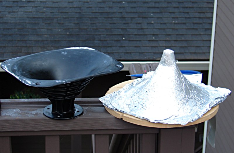
Here's a mold made from an XT1086. Note that the throat is muuuuuch longer than the OS waveguide, even though their coverage angles are comparable. The OS is 108x72, the XT1086 is 80x60.
- Home
- Loudspeakers
- Multi-Way
- Geddes on Waveguides