I'll be using the DRV134 for the time being. If I find myself with a balanced pre at some point down the road, it won't be necessary I suppose.
Room setup suggests that longer cable runs to the speakers (which will have the monoblocks AT the speakers) is the way to go - I have to route cables under the floor. 🙂
C
Room setup suggests that longer cable runs to the speakers (which will have the monoblocks AT the speakers) is the way to go - I have to route cables under the floor. 🙂
C
Regarding the SE to balance conversion, where would be the best stage to do the conversion for minimal sonic degradation? DAC/CD output/Preamp/Poweramp as in the Susy case?
Regards,
Ipanema 😕
Regards,
Ipanema 😕
As early in the chain as possible. 'Possible' is defined by which components accept balanced input.
Just a quick note to say that a pcb design is still in the works. Brian and I are getting the details hammered out, but as we are both very busy at work these days, its moving slowly. Please have patience with us.
Thanks, Terry
Thanks, Terry
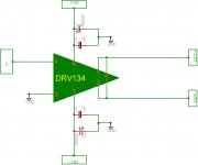
I made this DRV134 schematic to "convert" single ended to differencial output.
In the schematic it's +/-18V, but this is the max voltage that the chip can handle.
I will run it at +/-17V.
What do you think of the schematic ?
Ps: the 1000uF capacitor is Low ESR 25V.
In the schematic it's +/-18V, but this is the max voltage that the chip can handle.
I will run it at +/-17V.
What do you think of the schematic ?
Ps: the 1000uF capacitor is Low ESR 25V.
Attachments
I made a new version 😀
An externally hosted image should be here but it was not working when we last tested it.
I do not know what you exactly want.
Maybe the same thing I am thinking about...?
One day one guy said that he did not want to have a baby because of noise. Nevertheless, his wife was accidently pregnant. Oh my... he was informed by a doctor that she got twins. Girls.
Oh my.. she delivered the girls. But, strangely, he did not complain the expected noise. He said that his home was very quiet. The girls were very quiet. I thought why...? And, I found that it was due to very efficient CMRR.
Now I am studying this KIND OF cmrr to apply particularly for my noisy refrigerator. I hope i will suCceed and earn HELL OF money.
yEAH i'M DrUNK TONIGHT...
rEGARDS
I hope i will suCceed and earn HELL OF money.
A great story. I hope you earn the money. Or at least stay drunk longer 🙂
jh6you said:IyEAH i'M DrUNK TONIGHT...
rEGARDS
Cheers
 (or SKÅL as we say here in the north...)
Input resistors R5, R6
I have a question about the two 2K ohm input resistors (R5, R6). What are their purpose? Can I eliminate them if I use an input transformer?
I have a question about the two 2K ohm input resistors (R5, R6). What are their purpose? Can I eliminate them if I use an input transformer?
The 2Kohm input resistors are necessary to create a signal reference for the supersymmetric feedback loop.
Cheers, Terry
Cheers, Terry
The inputs of an X circuit are at virtual ground. Input resistance
sets the gain and provides an input impedance.
sets the gain and provides an input impedance.
BrianDonegan said:...and eliminating the numbers 5 and 6 causes all sorts of mathematical issues.
I think the leading issues might be
Infinite gain
zero i/p impedance
How do you drive that ? ...

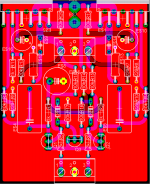
Here's a pic of a protopcb i made for the above schematic http://www.diyaudio.com/forums/showthread.php?postid=677880#post677880 Actually my father asked for advice as he was going to buy a new hifiset and i told him that i'd build him something good, so i endedup with the xgc 😀
An externally hosted image should be here but it was not working when we last tested it.
Congratulations. Very nicely looking pcb. I see only one pad for GND? You use copper plane so several more would not make difference in this case 😉
- Home
- Amplifiers
- Pass Labs
- GC SuperSymmetry