zinsula, cjd: I'm going to use carlos snubberized psu. I didn't see any other caps in the schematic. But it's obious to use some sort of caps from V to ground. How large, 220uF?
Bond them thermaly...not that easy with to-92. Do they get hot?
//v
Bond them thermaly...not that easy with to-92. Do they get hot?
//v
Carlos recommends you try various sizes IIRC. 220µF is what I'm using since they're on LM4780's and that value works out well since it's also used elsewhere in the circuit. I have plans for 100µF or so on a LM3886 chip-amp I'm working on. 220µF should be just fine though.
C
C
For the record, I'm using Pedja Rogic's regulated supply, with a Panasonic FC 1500uF cap between each PS pin and ground. Probably not optimal, and on my list of future experiments.
vit said:zinsula, cjd: I'm going to use carlos snubberized psu. I didn't see any other caps in the schematic. But it's obious to use some sort of caps from V to ground. How large, 220uF?
Bond them thermaly...not that easy with to-92. Do they get hot?
//v
He suggests 100µF and 100nF directly on the pins. Drawing is here http://www.diyhifi.org/forums/viewtopic.php?p=265#265
but the mentioned caps are not drawn on the schematic.
Regarding temperature- if I'm right, each transistor is dissipating 3.5mA*20V=70mW. TO-92 has around 250K/W, so they will be 250*0.07=17.5°C above ambient.
You can bond them with termal paste and a "shrinking hose(?)"
Dunno if it helps anything though, as you have C1/C2 which block DC.
Didn't get that at a first glance, therefore my suggestion.
Ciao, Tino
vit:
how're you getting power to the chips? Jumper wires?
I still don't see any caps at the chip pins (V+/V-) - or, are you attaching these completely off the PCB? 100µF electrolytic from V+/V- to G on each chip, with a .1µF as close to the chip pins as is reasonable. Though I could be mis-reading the layout some. 10kµF is good if you're regulating or going with one of the "snubber" layouts, and have the smaller caps at the chip. You can see on mine the 220µF/.1µF caps. I do not have the power boards here since I'm not yet sure what I'll be going with in the long run.
Also - this amp would be very quiet! You have nothing from the mute pin! You need a resistor from pin8 to V-. 10k should work.
C
cjd:
OMG, you are right, I forgot the mute pin!
Yes, power will be distibuted with jumper wires.
I will solder both the 220uF and 0,1uF caps directly to the legs of the chip. That's why you don't see them.
Thx mate!
OMG, you are right, I forgot the mute pin!
Yes, power will be distibuted with jumper wires.
I will solder both the 220uF and 0,1uF caps directly to the legs of the chip. That's why you don't see them.
Thx mate!
Where're they attaching to ground then? Unless you *really* need the space, I'd go with the 220's on the board personally. Your call though.
Mute pin, yeah. My initial schematics, for some reason I had it going to ground. Woulda been pretty quiet that way too.
 Gotta order parts soon.
C
Mute pin, yeah. My initial schematics, for some reason I had it going to ground. Woulda been pretty quiet that way too.
Gotta order parts soon.C
Hi
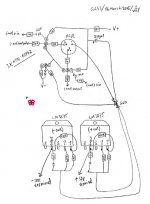
Here is my GCSS finished on the paper.
This is actually my production drawing.
I will replace ZTX with KSP42 (available in hand).
The rail voltages will be +/-15.
If found that 15V is too low,
I would increase the rail voltages,
using one 400VA toroidal for +30V supply
and another 300VA EI for –30V supply.
This transformer mixture is ok…!?!?
Attachments
Hi jh6you,
It might be better to run the o/p zobel networks separately to the earth hub - or perhaps join two zobel earths together and run one wire to the hub.
you could do the same with the other two earth wires from the two amps - join them together close to the amp and send one wire to the hub.If all is well the AC currrents to earth should be equal and opposite and so will cancel.
mike
SuperSymetry for the 4780
Has anyone designed a supersymetry circuit and board for the 4780? I have four, and would like to build one...
Thanks!
Has anyone designed a supersymetry circuit and board for the 4780? I have four, and would like to build one...
Thanks!
Re: SuperSymetry for the 4780
Did you read through the thread at all? I posted one up a page or two previous (though I'm still collecting parts so it hasn't been built yet).
edit: link to my post.
The PCB is still in a small state of flux as I look deeper into component sourcing. In particular, I may shuffle a bit to allow for slightly larger resistors and transistors.
Also, this assumes a high-cap power supply (whether regulated or "snubberized") off-board.
C
WorkingAtHome said:Has anyone designed a supersymetry circuit and board for the 4780? I have four, and would like to build one...
Thanks!
Did you read through the thread at all? I posted one up a page or two previous (though I'm still collecting parts so it hasn't been built yet).
edit: link to my post.
The PCB is still in a small state of flux as I look deeper into component sourcing. In particular, I may shuffle a bit to allow for slightly larger resistors and transistors.
Also, this assumes a high-cap power supply (whether regulated or "snubberized") off-board.
C
Yesterday, I finished construction of GCSS test version.
For safety of my speakers, I first checked offset voltages.
It seemed that both channels were instable and oscillating.
All of yours working with no this problem?
For safety of my speakers, I first checked offset voltages.
It seemed that both channels were instable and oscillating.
All of yours working with no this problem?
When I first started I had this problem, but after "Throwing away gain" as Nelson suggested the amp became stable. The schematic in post #240 is exactly what I am using now. Let's start by checking that you have the correct values for resistors R3-10. Also check the solder joints for R3,4,11 and 14. Cold joint there will cause instability.
Lastly, what voltage did you select for the power supply? I can do a check with my circuit model and see if that might be causing the problem.
Terry
Lastly, what voltage did you select for the power supply? I can do a check with my circuit model and see if that might be causing the problem.
Terry
Metalman
Thanks for your kind involvement.
The rails are +/-15V.
Oh my my... I found 4 resistors in my trouser pocket.
Last night I forgot soldering these, which resulted in too high closed loop gain and the instability. 😉
I will fix this tonight.
Regards
Thanks for your kind involvement.
The rails are +/-15V.
Oh my my... I found 4 resistors in my trouser pocket.
Last night I forgot soldering these, which resulted in too high closed loop gain and the instability. 😉
I will fix this tonight.
Regards
Still both channels instable.
I feel the 20K feedback resistor seems to be too big.
I will try again one week later.
Regards
I feel the 20K feedback resistor seems to be too big.
I will try again one week later.
Regards
How were you testing? i.e. Did you have the inputs open or connected to a source? Were you loading the output or leaving it open? If the outputs are left open the circuit will be unstable, so put a power resistor across the outputs when testing, I used a 10 ohm 25 watt ressitor.
Check the CCS and see if the voltage across the collector resistor is in the right range.
Lastly, are you using electrolytics or film caps for C1 and C2. The electrolytics have caused minor problems for some people.
Keep up the good effort, and I'll try to give you as much support as I can.
Terry
Check the CCS and see if the voltage across the collector resistor is in the right range.
Lastly, are you using electrolytics or film caps for C1 and C2. The electrolytics have caused minor problems for some people.
Keep up the good effort, and I'll try to give you as much support as I can.
Terry
Hi metalman
The test was on both input and output open.
Yes, eletrolytics.
Before I do further trouble shooting after coming back from one week away, I'd like to have certain time to think.
Let's keep discussion. Thanks.
Regards
The test was on both input and output open.
Yes, eletrolytics.
Before I do further trouble shooting after coming back from one week away, I'd like to have certain time to think.
Let's keep discussion. Thanks.
Regards
Hi metalman
My chronic disease is always "doing before thinking."
The problem seemed not due to the oscillation.
Since I reduced the rail voltages down to +/-15V, I should have reduced R1, R2 and R15 to about 400-500 ohms.
I will fix... soon after returning back to Shanghai.
Hmm...
See you.
Regards
---------
Hey man!!!! ... standing and laughing at me ... You should have told me!!!
- Home
- Amplifiers
- Pass Labs
- GC SuperSymmetry