Member
Joined 2002
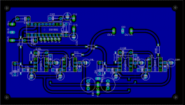
Gcollier said:And here is the PSU
How did you run the ULP ?
I tried
http://web2.callisto.twam.info/eng/index.php?page1=eagle3d
I cant figure it out.
Re: Re: Re: Re: Re: Re: Teasers
Carlos: I can tell it's a Krell by the sophisticated layout and the HUGE heatsinks 😉
Anyway, I took your suggestion and moved those caps...and it makes for a very nice single sided board. You need a few jumpers but it's not too bad! I made the decoupling caps a bit smaller something like the Vishay MKT 63V should work well here, I have a few and they would be a perfect fit. I left all the caps in the signal path alone.
I may actually do this double sided and just put the broken traces on the other side of he board, but if somone wanted to etch a single sided board it would be no problem at all. Now the other nice thing is that the groundpane is now completely onbroken so you won't need any vias or jumpers to keep everything connected.
So here it is PMA Preamp Beta 1! 😀
carlosfm said:
That's your choice.
Or you do it properly, or simply don't use good/fast op-amps.
The OPA627 doesn't sound decent that way.
If I would decide on the pinout of an op-amp, V+ would be at pin 5 and I would use the caps as you did.
But unfortunately nobody thought about that decades ago, and the chips back then didn't demand that, anyway.
My mini-"Krell".😀
Carlos: I can tell it's a Krell by the sophisticated layout and the HUGE heatsinks 😉
Anyway, I took your suggestion and moved those caps...and it makes for a very nice single sided board. You need a few jumpers but it's not too bad! I made the decoupling caps a bit smaller something like the Vishay MKT 63V should work well here, I have a few and they would be a perfect fit. I left all the caps in the signal path alone.
I may actually do this double sided and just put the broken traces on the other side of he board, but if somone wanted to etch a single sided board it would be no problem at all. Now the other nice thing is that the groundpane is now completely onbroken so you won't need any vias or jumpers to keep everything connected.
So here it is PMA Preamp Beta 1! 😀
Attachments
Better.
Now you should "isolate" the PSU from each chip by using a series resistor on each voltage rail/chip.😀
It also reduces the turn-on thump.
Now you should "isolate" the PSU from each chip by using a series resistor on each voltage rail/chip.😀
It also reduces the turn-on thump.
carlosfm said:Better.
Now you should "isolate" the PSU from each chip by using a series resistor on each voltage rail/chip.😀
It also reduces the turn-on thump.
Wouldn't that ruin the output impedance of the psu?
Alcaid said:Wouldn't that ruin the output impedance of the psu?
Actually it will reduce the noise of the PSU, as in effect that will be a CRC.
Not that you need a fancy PSU for op-amps, you don't, but the series resistors provide some isolation as the chips all share the same PSU.
Instead of the resistors, small chokes could be used.
Actually, the isolation resistors or coils are required if you have a crappy power supply. It does indeed ****-up the Zout (seen from the load, and that is the ONLY view that matters!), but if you have a supply that's not really regulated (like a set of emitter followers) you *may* need it.
If you have a competently designed *regulated* power supply, the resistors/coils make things worse, they effectively isolate the load from the low supply Zout, and thus *generate* all kinds of noise and signal-dependent ripple on the supply lines.
The resistor/coil stuff is an old relic from times when they were cheaper to use than a well-regulated supply. Unless you are really, really cost-cutting, a well-regulated, well implemented supply is the way to go.
Jan Didden
janneman said:Actually, the isolation resistors or coils are required if you have a crappy power supply. It does indeed ****-up the Zout (seen from the load, and that is the ONLY view that matters!), but if you have a supply that's not really regulated (like a set of emitter followers) you *may* need it.
If you have a competently designed *regulated* power supply, the resistors/coils make things worse, they effectively isolate the load from the low supply Zout, and thus *generate* all kinds of noise and signal-dependent ripple on the supply lines.
The resistor/coil stuff is an old relic from times when they were cheaper to use than a well-regulated supply. Unless you are really, really cost-cutting, a well-regulated, well implemented supply is the way to go.
Jan Didden
Just what I thought. But what would be a good regulator circuit for opamps? They have good PSRR, so what's the goal? low output Z? Linear output Z over the the whole frequency range?
Low noise? Exact regulation?
Propably all of them, but what's the way to go?
Shunt regulators?
Zener + emitter followers?
IC series regulators?
Unregulated but well filtered (RCRCRC, RCLCRC...)?
Upupa Epops said:Best way ? Read again, what Jan wrote 😀 .
Well, "a well-regulated, well implemented supply" doesn't tell me all that much. It rules out the non-regulated and the zener + emitter follower.
I dont know how the regulation is for the shunt regulators, but ICs are good in this aspect. Then there is noise..... 😕
janneman said:Actually, the isolation resistors or coils are required if you have a crappy power supply. It does indeed ****-up the Zout (seen from the load, and that is the ONLY view that matters!), but if you have a supply that's not really regulated (like a set of emitter followers) you *may* need it.
Jan, the problem is not so serious, is it?
I mean low value (10~22R) resistors.
Now... why not a set of regs for each chip?😀
I don't know where you got this fear. Ordinary VR have ripple rejection cca 60 dB, so for example 1 V ripple at input cause 1 mV at output. Ordinary opamp have PSRR 80 dB, so on output come from supply practicaly nothing. I say again, much more important is correct grounding. Read some publication about this 😎 . BTW, belive less to wizards.
Upupa Epops said:I don't know where you got this fear. Ordinary VR have ripple rejection cca 60 dB, so for example 1 V ripple at input cause 1 mV at output. Ordinary opamp have PSRR 80 dB, so on output come from supply practicaly nothing. I say again, much more important is correct grounding. Read some publication about this 😎 . BTW, belive less to wizards.
I was NOT talking about PSRR, read my posts again.
78xx/79xx are fine for me, with op-amps.
LM317/337 are better.
Not need to go fancier than this, for line-level applications.
Again, you mix and match and don't understand what I say.
You do, but you want to play.
It's your game, but I'm a grown-up man and I don't feel like playing.
I leave.
Enjoy.😎
EDIT: At least the PCB layout is a little better now...🙄
You can have both, if you wish. Nelsons article says something about it. But I am not sure it is strictly necessary to🙂zener or capacitance multiplier in the PSU?
I have used Nelsons Zener/capacitance multiplier, but only for poweramps and headphoneamps running ClassA. It surely removes any supply noise. But as we all know, opamps reject that noise by themself, a lot better than simple ClassA amps.
I would just go for something that I find nice. Thats what I do, when building something😉 PSU's are always given a hard time. I have yet to see a supply that most people can agree to as being well implemented and all that😱 But, in the end you do need one😀 😀 Here is mine, in case you forgot:
http://www.diyaudio.com/forums/showthread.php?s=&threadid=49619&perpage=10&pagenumber=7
Steen.🙂
steenoe said:
You can have both, if you wish....I would just go for something that I find nice. Thats what I do, when building something😉 PSU's are always given a hard time. I have yet to see a supply that most people can agree to as being well implemented and all that😱 But, in the end you do need one😀 😀 Here is mine, in case you forgot:
http://www.diyaudio.com/forums/showthread.php?s=&threadid=49619&perpage=10&pagenumber=7
Steen.🙂
I agree Steeno...let's re-invent the Jung regulator another day and focus on the preamp desigh. PSU's can be tweaked to death and still somone will complain about some minor aspect of it. For me it's going to be a LM317/337 with enough capacitance on the output to take care of most of the noise 😉 Simple, functional...and cheap! Besides I blew all my money on those expensive opamps! 😀
Hey, I hate to throw this in so late in the game, but I was looking for an easy way to use a rotary encoder with the DS1802. I came across this seemingly unrealted app note:
http://www.intersil.com/data/an/an1231.pdf
which shows how to wire up a panasonic mechanical rotary encoder (>$2 for Digikey) with some simple logic to yield Up and Down pulses (just cut out the DAC and insert the DS).
Anyone want to try to work this in? Looks like there is room on the board...
http://www.intersil.com/data/an/an1231.pdf
which shows how to wire up a panasonic mechanical rotary encoder (>$2 for Digikey) with some simple logic to yield Up and Down pulses (just cut out the DAC and insert the DS).
Anyone want to try to work this in? Looks like there is room on the board...
WorkingAtHome said:Hey, I hate to throw this in so late in the game, but I was looking for an easy way to use a rotary encoder with the DS1802. I came across this seemingly unrealted app note:
http://www.intersil.com/data/an/an1231.pdf
which shows how to wire up a panasonic mechanical rotary encoder (>$2 for Digikey) with some simple logic to yield Up and Down pulses (just cut out the DAC and insert the DS).
Anyone want to try to work this in? Looks like there is room on the board...
You can't do that...that the space for the microcontroller 😉
Actually feel free to modify away! If you want the latest eagle files let me know. I have a design for a manual control that I will post later...if anyone has some 3D modelling experience and would like to help me with this please let me know. The control will have volume balance and mute all controlled by a single knob, and should be very easy to build.
😀
I would love to see your plans for that!
Is it wring for me to be p***ed about Maxim sending me SMD's instead of DIPs? They are free samples after all. Ah, still p***ed. Guess I'll need the Eagle files to make it a SMD footprint. Can you post or mail them? I will post my changes.
Thanks!!
Is it wring for me to be p***ed about Maxim sending me SMD's instead of DIPs? They are free samples after all. Ah, still p***ed. Guess I'll need the Eagle files to make it a SMD footprint. Can you post or mail them? I will post my changes.
Thanks!!
Member
Joined 2002
WorkingAtHome said:I would love to see your plans for that!
Is it wring for me to be p***ed about Maxim sending me SMD's instead of DIPs? They are free samples after all. Ah, still p***ed. Guess I'll need the Eagle files to make it a SMD footprint. Can you post or mail them? I will post my changes.
Thanks!!
I can help some more i really want to get this preamp done for my gain clone's. : O ) ANd a digital rotary Volume would be cool..
Im useing eagle right now so any changes can be emailed to me and i can do them.
Jason
WorkingAtHome said:I would love to see your plans for that!
Is it wring for me to be p***ed about Maxim sending me SMD's instead of DIPs? They are free samples after all. Ah, still p***ed. Guess I'll need the Eagle files to make it a SMD footprint. Can you post or mail them? I will post my changes.
Thanks!!
A free sample is a free sample. I can change the layout for an SMD version of the DS1802 for you, no problem....I'll see what I can do tonight but I make no promises (the wife has me working on other "more important" projects. 😉 What package did Maxim send you? Like I said before I'll post the pictures for that volume control soon, I think the function would be more obvious if I had a 3D model of it though.
I have attached the new board files (still DIP) for anyone to play with. I hope that next week I should be able to put some more work into this project, and possibly get a prototype put together.
And again if anyone want's to add the rotary controller feel free.
Attachments
- Status
- Not open for further replies.
- Home
- Amplifiers
- Chip Amps
- GC Preamp Suggestions