The $10 or $9 additional price for TPA3116 means it is soldered on pcb? (3116=~$4 at Mouser). Regarding partskit: the resistors I think will have the least discussions, the 1nF's and 10nF's following. Some will argue the boottraps will matter much and then I will argue about the decouplingcaps, inputcaps and buffer elco's, inductors and main outputfiltercap 😀
The $10 or $9 additional price for TPA3116 means it is soldered on pcb? (3116=~$4 at Mouser). Regarding partskit: the resistors I think will have the least discussions, the 1nF's and 10nF's following. Some will argue the boottraps will matter much and then I will argue about the decouplingcaps, inputcaps and buffer elco's, inductors and main outputfiltercap 😀
Therein is the issue...design by committee.
The kit will contain parts to get the amplifier(s) working for a specific load based on TI data sheets (and some of my preferences).
I don't know where you got the $4 at mouser (unless you buy a lot of them)
You can all look up the price for 3116 in $CDN, add 13% tax and part of $8 shipping (Digi-Key) to see my cost.
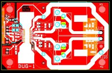
So far the changes form my original board layout are:
Input caps were 0805 are now 0805/1206/1210/through-hole @0.1"LS/0.037" holes.
power electrolytics were 0.4"dia/0.2"LS to 0.65"dia/0.3"LS mainly to accommodate higher output powers.
Power supply HF bypass were 0805, now are 1206.
Inductor footprint will take at least 5 different types and also has two sets of through holes.
Filter and snubber footprints (top side) are 1206 with exposed copper on the bottom ground plane for other larger parts.
Exposed copper below the input area for ground plane extension for those using really large input caps.
Startup mute circuitry.
Later
Doug
I think mouser recognises IP adress🙂 mouser adds 21% salestax for me, Digikey have funny way to calculate salestax after delivery, maybe other European buyers know how they do it, but for me most of times UPS will send me a bill for salestax later, which then always is around 10% 😀
example: 7th may Digikey delivered some parts here for 78.30 euros. UPS sent bill(+/- 7 weeks later)the other day for salestax: 7.35 euros. Dutch salestax is 21% like Mouser adds befor I pay. I am not complaining🙂
example: 7th may Digikey delivered some parts here for 78.30 euros. UPS sent bill(+/- 7 weeks later)the other day for salestax: 7.35 euros. Dutch salestax is 21% like Mouser adds befor I pay. I am not complaining🙂
Last edited:
Tl PT2313 version on Taobao/Aliexpress without those Elna's in input/output/input is a massive surprise, it isn't mine but I am listening to it now. Not sure why it sounds so good.
Are you referring to this http://www.aliexpress.com/item/Free...-50-W-with-Silent-Sleep-Design/1586764360.htm
Couple of quick questions Dug.
Will your board incorporate the mod around AVCC that abraxalito did separating pin 17?
I am a little unclear as to the resulting power available from PBTL. The datasheet says "MONO mode enabling up to 100W output power" and the circuit diagram shows 100watt into 2 ohm. Do you get 100watt into 4 or 8 ohm or is tho output reduced? I assume the LC filter will need adjustment for the impedance being driven, is this designed on same basis as straight BTL amplifier?
I'm also interested in how the 100W @2ohm translates into the output @ 8 ohms.
Here is the answer I got from irribeo - PBTL power is 1 to 1.5 watts above BTL, you could say they are equal.I'm also interested in how the 100W @2ohm translates into the output @ 8 ohms.
I would weigh against any addition except the bare necessities, something that fits the approach that was taken for the Subbu DAC (where a power on LED was considered the highest luxury the board would have)
A volume pot (with an option to bypass it) might be a good addition as most people would need it.
A LP filter on the other hand is something I consider to be surperfluous especially that there are so many different designs and topologies that are far from being universal and this is before considering the extra compelxity and cost that comes with it
Almost any amp benefits from an input filter and we are talking 4 parts here. The luxurious power LED could be omitted 😉 I must admit the spartan approach of Subbu V3 has been liked by many, myself included... Still V3 used 4 power supplies which is not exactly "bare necessities". It is a question of focus for quality instead of features. Now define quality please 🙂
Last edited:
How much time is left before I have to make a decision?
And, if I understand, the plan is for the TPA3116 IC to not come pre-soldered? If we're voting, I vote for it to be pre-soldered.
I'm leaning towards jumping in, but a little unsure if my soldering skills are up to it. The hacking I've done recently on the YJ blue/black board is the most "sophisticated" soldering work I've done to date.
How much time is left before I have to make a decision?
And, if I understand, the plan is for the TPA3116 IC to not come pre-soldered? If we're voting, I vote for it to be pre-soldered.
I'm leaning towards jumping in, but a little unsure if my soldering skills are up to it. The hacking I've done recently on the YJ blue/black board is the most "sophisticated" soldering work I've done to date.
There is an option for the IC to come supplied.
There is an option for the IC to come soldered.
I am also considering a Kit for a basic "get it running" level.
The deadline for next Monday is to fix the design and start final board layout.
I will buy more than enough boards to cover existing pledges.
Some people will drop out, some people will discover this thread later.
My risk.
But a TPA3116/8 PBTL will be available for DIY and that is part of the goal.
Doug
And, if I understand, the plan is for the TPA3116 IC to not come pre-soldered? If we're voting, I vote for it to be pre-soldered.
I'm leaning towards jumping in, but a little unsure if my soldering skills are up to it. The hacking I've done recently on the YJ blue/black board is the most "sophisticated" soldering work I've done to date.
While soldering smd chips might seem daunting, it's much easier than one might think provided the right technics and solder are used.
Just my 2 cents 😉
While soldering smd chips might seem daunting, it's much easier than one might think provided the right technics and solder are used.
Just my 2 cents 😉
I agree, but errors can be costly and require additional tools/experience to repair. (IMHO)
X2 or greater stereo goggles
Liquid flux
Very small tip iron at 690-700 deg F
Clamp the part down (my method for 3116)
Very thin solder
Rest both arms on the table or bench.
Secrets revealed.
🙂
I agree, but errors can be costly and require additional tools/experience to repair. (IMHO)
The extra risk with a GP situation is that the board is no longer available after you ruin it (or at least lack the skills to remedy a botched job).
Since we can get the board with the IC pre-soldered, please put me down for two (with pre-soldered tpa3116 IC).
Thanks DUG!
Soldered tpa will be nice.
In the other tread there was a link to another device TAS5756, amplifier part looks almost equal to 3118, but not sure if it is totally equal. With that in mind that chip that can process 25Mhz signals is decoupled with: 0.1uF+ 1uF+22uF+390uF (for PBTL). There are layout instructions in datasheet with maximum!!! distances for powersupply decoupling, I tried to measure and I think they are from mid solderpoint capacitor to chippin: max 2.5mm for 0.1uF, max ~6mm for 1uF, max ~7mm for 22uF and 10 to 12.5mm for 390uF. The first 2 positions on layout for DUG pbtl look ok, how far is the big elco away from chippins? BTW Now I am sure, I won't be using 1nF, closest to chip will be 0.1uF for me.
In the other tread there was a link to another device TAS5756, amplifier part looks almost equal to 3118, but not sure if it is totally equal. With that in mind that chip that can process 25Mhz signals is decoupled with: 0.1uF+ 1uF+22uF+390uF (for PBTL). There are layout instructions in datasheet with maximum!!! distances for powersupply decoupling, I tried to measure and I think they are from mid solderpoint capacitor to chippin: max 2.5mm for 0.1uF, max ~6mm for 1uF, max ~7mm for 22uF and 10 to 12.5mm for 390uF. The first 2 positions on layout for DUG pbtl look ok, how far is the big elco away from chippins? BTW Now I am sure, I won't be using 1nF, closest to chip will be 0.1uF for me.
Pre filter the EVM module also has output connected through 330pf and 10 ohm to ground, that just happens to be connected to bootstrapcap too. Only board I recall that copied this is SMSL amp. What is supposed to be the function of this?
I have added the snubber directly on the outputs as in the ap note.
The R is 1206 and the C is 0805. (I am not using 0603 on this board)
🙂
Also probably the last change:
Avcc has been separated with a series R and bypass cap. (both 0805)
This will allow people to at least try this mod without hacking up the board. Anyone that does not wish to use it can either jumper the resistor or connect all three pins on the IC together.
🙂
Last edited:
- Status
- Not open for further replies.
- Home
- Group Buys
- GB for TPA3116/8 PBTL bare pcb