Anything 4 or over sounds great to me. I normally build preamps with 6 inputs but in truth never use more than 4.
FWIW, a rotary switch would be a nice way to go. If you use a 2 pole 4, 5 or 6way switch, but don't switch the grounds, you can use the other pole to switch some LEDs - handy for indicating which input is selected. Having it off board allows for easier casework, more ways of mounting the switch etc.
However, if its a huge hassle, I repeat what I have found before: a simple rotary switch sounds just as good as a relay based selector. I know that may be at variance with others here.
I etched my board tonight for a ligthspeed type attenuator but using a teddyreg to give a super quiet stable supply. I am now in a quandry! I have this nice B1 board from pass sitting here waiting to be built but then theres this group buy!!
What do I do!?
Fran
woodturner-fran said:
I repeat what I have found before: a simple rotary switch sounds just as good as a relay based selector.
I have this nice B1 board from pass sitting here waiting to be built but then theres this group buy!!
What do I do!?
Fran
Original B1 boards?
Maybe keep them unsoldered as collectors items, with active devices 😉
Looks very good🙂
If I want a simpler pre without relays, I have my LDR 😀
Im all for that
Double bridge gone again?
If I want a simpler pre without relays, I have my LDR 😀
Im all for that
Double bridge gone again?
Xaudiox,
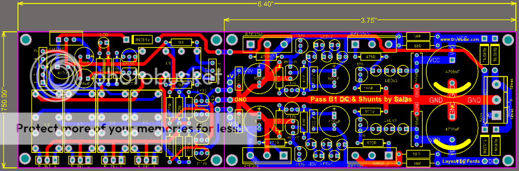
I really like the 4 relay-switched inputs! Very cool!
What happened to the dual bridge?
Thanks for doing this! I am green with envy of your talents.
Bill
I really like the 4 relay-switched inputs! Very cool!
What happened to the dual bridge?
Thanks for doing this! I am green with envy of your talents.
Bill
MashBill said:Xaudiox,
What happened to the dual bridge?
Bill
If doing split ground lines with double bridge, maybe just till between the supply caps, and common ground there after
It should result in better isolation of trafo/mains noise and clean ground
Well, I dont remember too good, but I think it was something like that
oppss i forgot to add pads for the volume control (thanks jean-paul)..
i'll update it tonight..
thanks
i'll update it tonight..
thanks
... and some diodes (1N4148) in // with relay coils maybe.
P.S. why not TQ2? they are smaller, as good as DS2E and easy to fine (yes, a bit $$$)
P.S. why not TQ2? they are smaller, as good as DS2E and easy to fine (yes, a bit $$$)
This latest incarnation is the one I really like. I've spent some time checking and found nothing amiss, but then again, I'm not that good at proofreading circuit boards.
Thanks for doing all this work and for your patience with the incoming requests.
Thanks for doing all this work and for your patience with the incoming requests.
thanks to all of you too..its still a long way to go..😀
looks like from the current reactions of the other members.. it seems that it makes sense if we could just separate the B1 and shunt psu..I, same with the other members is very interested with the psu section..
what do you think guys?
P.S. if someone know how to create a wiki page.. please please start a wiki page for this groupbuy.. i've been trying all day but it seems i can't find a way to do so...
thnks
woodturner-fran said:
I etched my board tonight for a ligthspeed type attenuator but using a teddyreg to give a super quiet stable supply. I am now in a quandry! I have this nice B1 board from pass sitting here waiting to be built but then theres this group buy!!
What do I do!?
Fran
Fran,
At the moment I am using a Lightspeed as the volume control on the B1 Buffer, excellent sound - so I suggest finishing it.

I am waiting for more LDRs and then this new B1 board (which is looking better hour by hour) and I will then put them together in the same way.
Alan
Salas
have you tried PS section working range of your design I have seen that you are using 37 V out
So from your experience Is 5 - 40 V out normal voltage range of this design and also what Is current range
have you tried PS section working range of your design I have seen that you are using 37 V out
So from your experience Is 5 - 40 V out normal voltage range of this design and also what Is current range
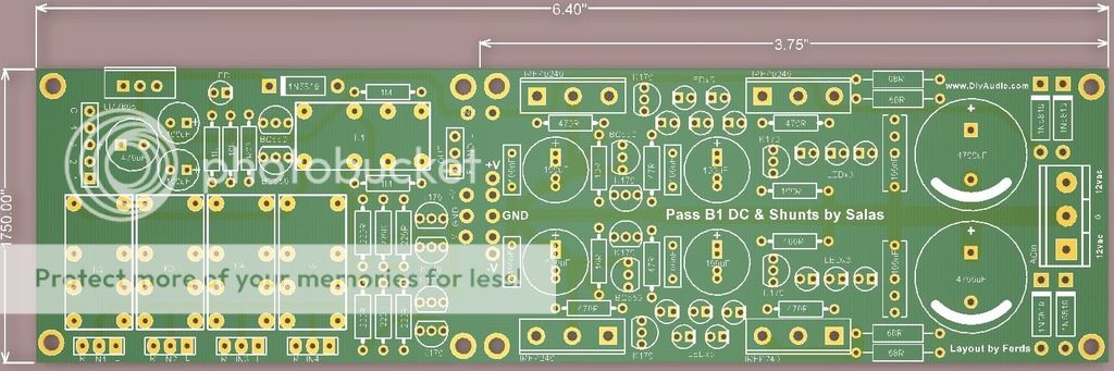
Very nice, Ferds! 
My very small suggestion:
I would like to see additional footprints for TO-220 cased diodes
(my favorites are MUR8xx)
My very small suggestion:
I would like to see additional footprints for TO-220 cased diodes
(my favorites are MUR8xx)
Michi124 said:Very nice, Ferds!
My very small suggestion:
I would like to see additional footprints for TO-220 cased diodes
(my favorites are MUR8xx)
Good thinking.
Wow this is really moving along and looks great, kudos to the design team!
My issue is that it has now gone well past anything that I need, or want. I truly wanted an nice swell sounding buffer to complete my system I already have selector and attenuator, etc and was hoping to drop this in there.
I was really happy with the original. Does anyone else think this too? Perhaps we could see how many are and get a "splinter" GB going.
These are just my thoughts and do not in anyway want to take away from the great work going on!!
samoloko said:Salas
have you tried PS section working range of your design I have seen that you are using 37 V out
So from your experience Is 5 - 40 V out normal voltage range of this design and also what Is current range
Not with leds, I haven't. Adding features, using it as a solo shunt, re routing it, is beyond my prototypes, from there on its in the hands and likings of the GB-PCB team, and I can't spec anything or know it will be working flawlessly as a whole. It has gone public now, looks like all the things wanted to be done are 99% feasible without problems, but the way it goes I would suggest that a working prototype is made and tested first to avoid the odd gnd buzz or something not responding. Just my 2C.
billyk said:Wow this is really moving along and looks great, kudos to the design team!
My issue is that it has now gone well past anything that I need, or want. I truly wanted an nice swell sounding buffer to complete my system I already have selector and attenuator, etc and was hoping to drop this in there.
I was really happy with the original. Does anyone else think this too? Perhaps we could see how many are and get a "splinter" GB going.
These are just my thoughts and do not in anyway want to take away from the great work going on!!
The reactions towards a complete design are positive. Maybe you can send a PM to xaudiox for the files of the previous "buffer/power supply" version if you promise to use them only for yourself. I have no idea if he is willing to share them.
The project is indeed moving to a complete PCB or 2 PCB's with all parts and sections on them.
Salas said:
It has gone public now, looks like all the things wanted to be done are 99% feasible without problems, but the way it goes I would suggest that a working prototype is made and tested first to avoid the odd gnd buzz or something not responding. Just my 2C.
Agreed for 100 %. Maybe xaudiox can comment too. It can not be that about 200 PCB's wil be made without having been tested.
If its a single sided board, maybe someone could etch one at home and try it out before putting in the order for a big lot?
Fran
Fran
If anyone is planing on doing this,Im in for at least 2 boards..Maybe you can send a PM to xaudiox for the files of the previous "buffer/power supply" version if you promise to use them only for yourself. I have no idea if he is willing to share them.
Maybe we should do a poll wich boards people would like?
- Home
- Group Buys
- GB for DC coupled B1 buffer with shunt PSUs