Yes there is room for three boards. The link is aluminum standard American power supply filter socket chassis DIY shell box-in Amplifier from Consumer Electronics on Aliexpress.com | Alibaba Group
Enjoy
Enjoy
Hi drpro,
Very nice looking. Love that enclosure. What is the breaker?
I was going to put a breaker in mine but went with just a fuse holder due to cost.
Very nice looking. Love that enclosure. What is the breaker?
I was going to put a breaker in mine but went with just a fuse holder due to cost.
drpro,
hello, what gauge wire did you use in the case/build that you show?
did you use plastic/ nylon washer between the pcb and the case? also, how do hook up the led?
thanks,
drmike (a real rookie)
hello, what gauge wire did you use in the case/build that you show?
did you use plastic/ nylon washer between the pcb and the case? also, how do hook up the led?
thanks,
drmike (a real rookie)
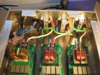
I used 12 and 14ga, basically what I had on hand. I used no plastic washers. The LED came with the socket chassis and included a diode and resistor in one leg so you can connect directly to the AC line.
I finally finished and tested mine and its working perfectly.
The DC blocker is only hooked up to the 17A bourns coil that goes to the power amp.
12awg wire was used only because I had some and the quick disconnects for easy changes if needed.
Teflon coated 14awg wire would be much easier to work with IMO.
All in all, with this being my first DIY project I'm very happy 🙂.
Thanks Destroyer OS and Per-Anders for all your help.
I'll try and do a review in the future.
Attachments
Last edited:
Looks real nice AmpUtator!
If you can, post impressions with/without your powerstation connected.
If you can, post impressions with/without your powerstation connected.
I have a soldering question.
I rarely have a solder joint that only takes 2-3 seconds like I've seen so many times before online.
In fact, sometimes it seems to take 30-60 seconds and still fails.
I clean the tip all the time, use liquid flux, a Hakko station at 750F, and Kester 63/37.
What I've been doing is soldering the coils and fuse clips first thinking they take a lot of heat and it's best to get them
out of the way before soldering the small components.
Am I doing this wrong?
Because I solder the big stuff first, am I making it harder to heat up the joints for the smaller components?
Thanks for any help.
Last edited:
When soldering large copper traces, you need to use a larger tip (more mass). Small tip will take forever to heat that surface. How many watts is your Hakko station? 60-80 Watts?
I think it's 70 watts, 900F max. It's a Hakko FX-888D.
I've tryed 5 different tips. I still have the same problem but's it's only on those little tiny eyelet's about 1/8 diameter. Larger eyelets I seem to be okay.
I've tryed 5 different tips. I still have the same problem but's it's only on those little tiny eyelet's about 1/8 diameter. Larger eyelets I seem to be okay.
More heat. 775F for this stuff will work better. You may even get closer to 800 depending on how many watts the iron is (how fast it’ll lose heat and regain on contact).
You want the joint to heat fast, and not get tons of thermal spread. Waiting 30 seconds just wears down the PCB board and can cause lifting/bubbling etc.
I suggest to get these big connector and cmc joint going you put a dab of solder on the tip and then press that dab into the joint. It is effectively like upsizing the tip. Then you can try to feed some solder into it, may take a couple seconds. If it pools up a little that is ok, just slow down and wait for it to plop it onto the lead and PCB so you know it isn’t cold, and then how much more you’ll need if any. The worst thing that happens is doing too much and not being able to tell if its cold or just has too much solder.
I would run my iron even hotter but resin will run all over and then the solder won’t flow nicely. That is the reason I rarely push past 775F, and have to really be careful about it. More often I go over when trying to remove a wire from binding post or something.
Oh, and I do CMC last, and WECO second to last with the top unscrewed a little. For the CMC I may crank the heat and touch it for a few moments prior to the joint. Maybe even if see if solder will run on it first before pushing down towards the via pad (eyelet).
hello,
can i use nylon screws and nuts to attach the pcb to an aluminium case? what type of fuse should be used?
thanks,
drmike
can i use nylon screws and nuts to attach the pcb to an aluminium case? what type of fuse should be used?
thanks,
drmike
For those with experience with the felix, have you tried it with power subwoofers?
I have a pair of 400W class D powered subwoofers in my system and thought of running each through a felix with either the 10AMP comoco or the 17AMP bourns. Any impressions?
I have a pair of 400W class D powered subwoofers in my system and thought of running each through a felix with either the 10AMP comoco or the 17AMP bourns. Any impressions?
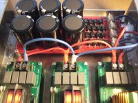
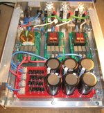
My take on a larger box with multiple outlets for all of the extras in the sound system.
drpro,
Not to be a know it all,
but if you have a metal case, the hydro earth (ground) must be attached to the
metal case with a dedicated machine screw.
From then from that machine screw, I would recommend connecting
the grounds to the outlets using a star configuration.
Your grounds are daisy chained from one outlet to then next - I'm not sure if
that's to code.
Also, I would recommend installing the fuses.
If one filter is over loaded, while the other one has no load,
the breaker might not trip.
.
- Home
- Group Buys
- GB: Fo-Felix EMI Filter for AC mains 120/230v; By Folsom