You won...! -the right to make the board wider, and maybe implement dual mosfets at each end?
Arne K
Arne K
You may not believe me, but I was already thinking along those lines - the only problem is that I need to write more stuff on the boards, so that people don't get confused. 😉
So unless I trace myself into a corner I'll add extra fets.
So unless I trace myself into a corner I'll add extra fets.
You won...! -the right to make the board wider, and maybe implement dual mosfets at each end?
Arne K
Yes!!!
You won...! -the right to make the board wider, and maybe implement dual mosfets at each end?
Arne K
Myself , I think the original circuit is fine. Having the FETs on the end is fine but not absolutely neccessary. You could go overboard trying to include everything. Remember KISS.
Well I didn't take the "end" part to literally - I thought I could increase the board size by just adding a new set of mostfets. You could then use them or ignore them.
If possible, moove the thermistor between the mosfets, so you easily can choose, if only using one pair.
Arne K
Arne K
If possible, moove the thermistor between the mosfets, so you easily can choose, if only using one pair.
Arne K
Or one could add a second set of holes, but I think in operation only one is needed per rail.
With two pairs of outputs some of the simplicity is lost and you'll need a lot more heatsink too.
Sure the you need more heat sink if you run more current. You don't have to do that just because there are more output devices. And I planned on adding an extra set of thermistor holes for the other mosfet. You only have to use one set though.
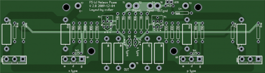
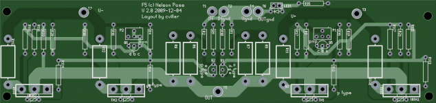
Ok, here is what I have come up with. I need to clean the silk screen, but besides this it should be pretty functional.
The board is 190x45 mm. You may notice that I have placed the thermistors differently. This is to make it easier to mount. The drawback is that I had to run traces in between the mosfet footprints, but this should not pose any problems IMO.
Any comments?
The board is 190x45 mm. You may notice that I have placed the thermistors differently. This is to make it easier to mount. The drawback is that I had to run traces in between the mosfet footprints, but this should not pose any problems IMO.
Any comments?
Attachments
Looks nice with the parts spread out a bit. Not that I would use two pair of outputs but are the pairs too close together?
Why would someone use two pairs of outputs with the same current as one pair?
Why would someone use two pairs of outputs with the same current as one pair?
Last edited:
Looks nice with the parts spread out a bit. Not that I would use two pair of outputs but are the pairs too close together?
Why would someone use two pairs of outputs with the same current as one pair?
Well I have added the extra footprint mostly for people who likes to use more devices - as an extra option. But you are right if you run them at full throttle, you'll need to make sure you can transfer the heat away. You can use a copper spreader if you like.
I think people who wants to do this will probably end up running each device at 700 1000mA or so - if you want to push it further you need prohibitively large heatsinks imo.
I have updated my order site - added the new layout and made an GB List page, where you can follow who signs up (and pays).
Order page:
GB order page for cviller
Group buy list:
Group Buy status page
I am considering also doing the F4 - would that be of any interest?
Order page:
GB order page for cviller
Group buy list:
Group Buy status page
I am considering also doing the F4 - would that be of any interest?
F5 board
Hi all
I'm a newbie here.
An old plan to build the f5 so i'd like to have such a blue board. I have seen it's now out of stock but if anyone has a spare i'd be grateful.
Karoly
Hi all
I'm a newbie here.
An old plan to build the f5 so i'd like to have such a blue board. I have seen it's now out of stock but if anyone has a spare i'd be grateful.
Karoly
Hi Karoly,
You could join in on the gb of the new design - read post 1017. The boards will be blue again - its just my pcb software that has a preference for making green pngs.
You could join in on the gb of the new design - read post 1017. The boards will be blue again - its just my pcb software that has a preference for making green pngs.
Hi Cviller,
Have you tried the double output modification? I did and it didn’t sound as good as a single pair of output devises. My theory about why this occurred is that it increases the open loop gain hence the amount of feedback in the circuit. The nice sound field moved up front and wasn’t as appealing to me.
What do you think about adding a casscode devises for the input?
Thanks,
- Status
- Not open for further replies.
- Home
- Group Buys
- Gb: F5 Pcb