Hi All,
I have been asked quite a few times if I had any F4 boards available or if I would do a GB. So after having enjoyed doing the http://www.diyaudio.com/forums/group-buys/134554-gb-f5-pcb.html, I could just as well make some F4's. 😉
In this thread, I would like to hear if people would be interested in such a GB.
Here is the service manual btw:
http://www.firstwatt.com/downloads/f4_om.pdf
Christian
I have two questions:
1) Do you have a cost estimate?
2) How many boards are required to make a fully balanced amp?
Thank you
Eric
1) Do you have a cost estimate?
2) How many boards are required to make a fully balanced amp?
Thank you
Eric
If you want to make a fully balanced amp you'll need four channels - four boards.
The board is larger than the F5, so I think I have to set the price at $9 per board.
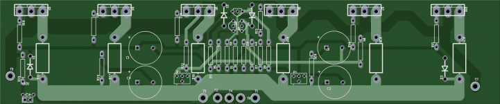
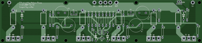
The board will be 230x50 mm and the spacing between the mosfets is 4cm.
I have a Group Buy status page here, ready for paid sign-ups.
The board is larger than the F5, so I think I have to set the price at $9 per board.
The board will be 230x50 mm and the spacing between the mosfets is 4cm.
I have a Group Buy status page here, ready for paid sign-ups.

i'm not an expert as far as pcb layout is concerned , but don't you think the input jfet pair is far to close to the power trany and radiator as well?
those jfets aren't zero tempoco
I would try to move them away from power trany as much as you can
those jfets aren't zero tempoco
I would try to move them away from power trany as much as you can
Hi dodo, I agree, but most people mount the board flat on the heatsink with 5mm spacers and then the fets will not actually be that close to the input devices. So for most it is not really an issue, but I will consider it - perhaps I can split the row of resistors and move them up.
F4 pcb
cviller
Two boards for me.
I made a F4/Aikido stage nearly one years ago according to the PCB you suggested in # 122. This stage work nicely together with my modded
DCX 2494 in the 60 - 600 Hz range on my Magnepan 1.6.
Now I am curious to test how F4 will behave as a headphone amplifier for my AKG 701. It is for this purpose I need two new boards.
Eivind Stillingen
Sounds like a great plan! 😀
I already have prepaid signups for 30 F4 boards (Group Buy status page).
I already have prepaid signups for 30 F4 boards (Group Buy status page).

Great Jim - if you want to sign up for the gb, you can do so at my fancy order site ( GB order page for cviller ). It is hooked up to paypal so I don't have to send invoices. 😉
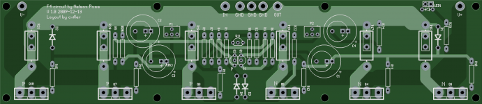
There is a label for a C103 capacitor that may be a mistake. On your layout it is under the C3 cap, but I do not find this on Nelson's F4 schematic.
Thanks
Jim
Thanks
Jim
Hi JimT, thanks. I'll remove the number. In my program all parts must have unique refdes and I wanted to add 5 mm cap holes, so thats why I had to add C103. I just need to turn off the label.
- Status
- Not open for further replies.
- Home
- Group Buys
- Gb: F4 pcb