Hello, repairing my brothers PSP3500.1D (or trying to). Issue in the title.
Tools I have: Multimeter (has diode mode, beep, etc), soldering iron
How it happened: He was listening to music at a low volume, shut off the car and went to the shops, when he came back the amp was dead.
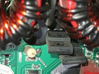
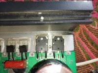
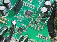
What I've done: Opened it up, found a IRFB7437 with the drain leg melted (see image below). Its 4.7ohm (4R7) gate resistor also was dead. Replaced both, still goes into protect.

Diagnostics:
There is no short between the RCAs and speaker outputs
There is an increasing resistance (goes from ~0 to ~135ohm) between the power and ground terminal.
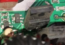
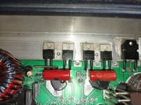
There is an increasing resistance (goes from ~0 to ~135ohm) between the drain and source (2nd and 3rd pin left to right) of all these fets (see image)
Rest of the fets seem fine

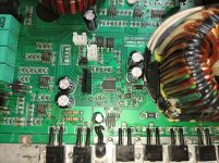
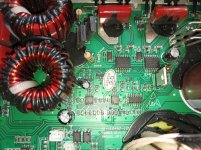
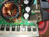
Other side of the amplfier:

I hope we will be able to find the issue, thank you in advance.
Tools I have: Multimeter (has diode mode, beep, etc), soldering iron
How it happened: He was listening to music at a low volume, shut off the car and went to the shops, when he came back the amp was dead.
What I've done: Opened it up, found a IRFB7437 with the drain leg melted (see image below). Its 4.7ohm (4R7) gate resistor also was dead. Replaced both, still goes into protect.
Diagnostics:
There is no short between the RCAs and speaker outputs
There is an increasing resistance (goes from ~0 to ~135ohm) between the power and ground terminal.
There is an increasing resistance (goes from ~0 to ~135ohm) between the drain and source (2nd and 3rd pin left to right) of all these fets (see image)
Rest of the fets seem fine
Other side of the amplfier:
I hope we will be able to find the issue, thank you in advance.
Last edited:
Yes, about 5v on the pin 1
Unknown freq on pin 2, as my oscilloscope is an arduino 😂
heres a screenshot from the UI, maybe can calculate it, as the time is known, the voltage is going thru a ~65.5x voltage divider as i didnt know how high of a voltage i would be dealing with on the rails

Unknown freq on pin 2, as my oscilloscope is an arduino 😂
heres a screenshot from the UI, maybe can calculate it, as the time is known, the voltage is going thru a ~65.5x voltage divider as i didnt know how high of a voltage i would be dealing with on the rails
Not very high res, so just took more, but closer shots. Basically took shots of the entire board
Attachments
-
 IMG_20240427_115820.jpg355.9 KB · Views: 14
 -
 IMG_20240427_135037.jpg311.9 KB · Views: 17
 -
 IMG_20240427_134536.jpg663.2 KB · Views: 13
 -
 IMG_20240427_134544.jpg619 KB · Views: 13
 -
 IMG_20240427_134552.jpg640.3 KB · Views: 13
 -
 IMG_20240427_134601.jpg595 KB · Views: 14
 -
 IMG_20240427_134609.jpg586.5 KB · Views: 12
 -
 IMG_20240427_134729.jpg366.6 KB · Views: 12
 -
 IMG_20240427_135518.jpg528 KB · Views: 15
I've been trying to find a diagram that's close and this amp is a lot of parts from the Brazilian amps, unfortunately, a lot of different models.
I'll keep looking. Hopefully someone will see this and is more familiar with the Brazilian amps than I am.
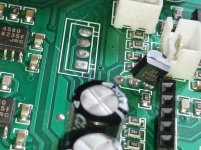
If you try to power up, at the instant that you apply remote voltage, do you see any sort of pulses of DC or square wave on the inputs of the 27324 PS driver IC?
Does it go into protect before you apply remote voltage?
I'll keep looking. Hopefully someone will see this and is more familiar with the Brazilian amps than I am.
If you try to power up, at the instant that you apply remote voltage, do you see any sort of pulses of DC or square wave on the inputs of the 27324 PS driver IC?
Does it go into protect before you apply remote voltage?
It only powers up and goes into protect when the remote voltage is applied. No remote is no power up like it should be.
I dont see any dc voltage, but i do see pulses of something, possible that its square wave that is too fast for the arduino. The pulses stop after the amp goes into protect. It goes like: remote applied, then the 3 leds (power, clip, protect) turn on after eachother, until the power and protect start flashing.

I dont see any dc voltage, but i do see pulses of something, possible that its square wave that is too fast for the arduino. The pulses stop after the amp goes into protect. It goes like: remote applied, then the 3 leds (power, clip, protect) turn on after eachother, until the power and protect start flashing.
- Home
- General Interest
- Car Audio
- GAS PSP3500.1d going into protect