With the diamond, you can replace the input pair on the OPS with cascoded jfets (despite the absence of the thoshibas there's still good pairs produced for something like this), then you can loose the buffer between the stages.
Still impressed by your voltage stage.
Still impressed by your voltage stage.
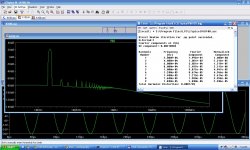
https://sites.google.com/site/opampbasedamp/diamond1.png
THD20K 0.018803% 100W 4ohm and only 150mA total bias
THD20K 0.018803% 100W 4ohm and only 150mA total bias
https://sites.google.com/site/opampbasedamp/diamond1.png
THD20K 0.018803% 100W 4ohm and only 150mA total bias
Yes, but did you simulate it at 1 W, it's even worst then at 100 W, and harmonic distribution is not good at all. In my opinion to get quite low distortion, euphonic harmonic distribution and that it works with no GNFB, a way to go is Class A OPS. I would be happy if someone design Class B(AB) OPS with similar properties as the Class A is not eco friendly.
With the diamond, you can replace the input pair on the OPS with cascoded jfets (despite the absence of the thoshibas there's still good pairs produced for something like this), then you can loose the buffer between the stages.
Still impressed by your voltage stage.
You mean like this? http://www.diyaudio.com/forums/solid-state/255819-gainwire-class-poweramp-ngfb.html#post3918601

Yes, but did you simulate it at 1 W, it's even worst then at 100 W, and harmonic distribution is not good at all. In my opinion to get quite low distortion, euphonic harmonic distribution and that it works with no GNFB, a way to go is Class A OPS. I would be happy if someone design Class B(AB) OPS with similar properties as the Class A is not eco friendly.
Hi Damir, this is a great development, I'm following regularly.
From my perspective, in no GNFB environment, the most valid alternative to class "A" is "AB" with error correction.
Here is an old thread related to it:
Error correction topologies thread
What do you think?
Cheers,
Valery
This is my NonGNFB amp prototype, final version will have 2-3 pairs of njw
Buffer - classAB bjt with HEC
https://plus.google.com/photos/106882583920049206569/albums/6022849719952718449
Frontend
https://plus.google.com/photos/106882583920049206569/albums/6023954203589784513
Buffer - classAB bjt with HEC
https://plus.google.com/photos/106882583920049206569/albums/6022849719952718449
Frontend
https://plus.google.com/photos/106882583920049206569/albums/6023954203589784513
Hi Damir, this is a great development, I'm following regularly.
From my perspective, in no GNFB environment, the most valid alternative to class "A" is "AB" with error correction.
Here is an old thread related to it:
Error correction topologies thread
What do you think?
Cheers,
Valery
Valery thanks for your interest. I simulated some Hawksford EC OPSs and some other types of OPS(buffers) with 100% NFB and I think in some way those OPSs brake No GNFB rule as uses a NFB to lower THD. I know that CFP is NFB but only locally(?). And I never got good harmonic distribution if I remember correctly.
Damir
This is my NonGNFB amp prototype, final version will have 2-3 pairs of njw
Buffer - classAB bjt with HEC
https://plus.google.com/photos/106882583920049206569/albums/6022849719952718449
Frontend
https://plus.google.com/photos/106882583920049206569/albums/6023954203589784513
This looks as finished amp. How have you found the sound?
Your FFT are somehow flawed, harmonics are not showed. Could you show your .asc files here?
This looks as finished amp. How have you found the sound?
Your FFT are somehow flawed, harmonics are not showed. Could you show your .asc files here?
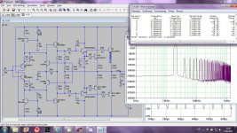
sim 20k 40Vpp into 4
Attachments
sim 20k 40Vpp into 4
This is my simulation, I used Cordell's models, readjusted the bias and THD is even a bit lower, but I don't like the harmonic distribution. This shows why I think that HEC is so good for the No GNFB amps.
Attachments
Yes, but did you simulate it at 1 W, it's even worst then at 100 W, and harmonic distribution is not good at all. In my opinion to get quite low distortion, euphonic harmonic distribution and that it works with no GNFB, a way to go is Class A OPS. I would be happy if someone design Class B(AB) OPS with similar properties as the Class A is not eco friendly.
Effectively , lower power is not good.
Low quiesent current is better for High power, High current is better for low power.
It may be a compromise
Yes, but did you simulate it at 1 W, it's even worst then at 100 W, and harmonic distribution is not good at all. In my opinion to get quite low distortion, euphonic harmonic distribution and that it works with no GNFB, a way to go is Class A OPS. I would be happy if someone design Class B(AB) OPS with similar properties as the Class A is not eco friendly.
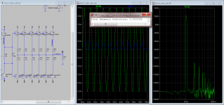
It's possible to design a class ab output stage with similar sonic characteristics of class A with less power waste, in my personal view the way to go is instead of using only one or two pair of power transistor at output, use several medium power transistors like the cheap 45h11 with low emitter resistors (0.1 ohms), in this way the crossover distortion happens at much higher output power.
This image is from the output stage of a test circuit of a new error correction that I am developing, I am in the process of simplifying the circuit to make it more DIY friendly when its done I will publish the circuit. The output transistors quiescent current is only 110mA per device, and even with 20V out in 8 ohms load (25W) the output stage have not switch off the output transistors, so the harmonics are very good with only 2º and 3º lower than 120db from the fundamental.
And ofcourse I also find error correction of the output stage a very elegant technique to linearise this problematic stage. 😎
Attachments
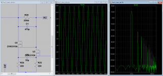
0.001783% 1W
0.012505% 100W
6mA 22mA 340mA
https://sites.google.com/site/opampbasedamp/diamond3.png
6mA 22mA 666mA : (R3=43)
0.000680% 1W
0.011159% 100W
0.012505% 100W
6mA 22mA 340mA
https://sites.google.com/site/opampbasedamp/diamond3.png
6mA 22mA 666mA : (R3=43)
0.000680% 1W
0.011159% 100W
Last edited:
0.001783% 1W
0.012505% 100W
6mA 22mA 340mA
https://sites.google.com/site/opampbasedamp/diamond3.png
6mA 22mA 666mA : (R3=43)
0.000680% 1W
0.011159% 100W
UltimateX86, if we omit the emitter resistors from the output the distortion will be lower but the problem is that in doing so the stage becomes thermally unstable, so in practice those resistors can not be omitted.
I really don't recommend the Sziklai pair for class AB, because the distortion at the crossover region is worst that what can be achieve with the darlington pair. In class A the Sziklay is more linear than the darlington, but again I personally don't recommend class A (just ecological issues of course 🙂 ).
It's possible to design a class ab output stage with similar sonic characteristics of class A with less power waste, in my personal view the way to go is instead of using only one or two pair of power transistor at output, use several medium power transistors like the cheap 45h11 with low emitter resistors (0.1 ohms), in this way the crossover distortion happens at much higher output power.
This image is from the output stage of a test circuit of a new error correction that I am developing, I am in the process of simplifying the circuit to make it more DIY friendly when its done I will publish the circuit. The output transistors quiescent current is only 110mA per device, and even with 20V out in 8 ohms load (25W) the output stage have not switch off the output transistors, so the harmonics are very good with only 2º and 3º lower than 120db from the fundamental.
And ofcourse I also find error correction of the output stage a very elegant technique to linearise this problematic stage. 😎
You don't show whole schematic and it's not easy to comment it. It is not very ecological to use 660 mA total bias either.
Could you explain your use of drivers unusual high cap (C3)?
- Status
- Not open for further replies.
- Home
- Amplifiers
- Solid State
- GainWire-CLASS-A-poweramp NGFB