Re: What sounds superiror PSU board closest to AMP or to Transormer
Thank you, I hope to see you post pictures of a finished amplifier soon.
I would think that it would be best to keep the power supply board near the transformer.
--
Brian
earsandeyes said:Brian, you did a beautifull job. Thanks to you and Meredith. Amp One is now soldered, will start wiring up and listening tonight (I hope)
🙂
Thank you, I hope to see you post pictures of a finished amplifier soon.
I would think that it would be best to keep the power supply board near the transformer.
--
Brian
The DC offset is ~60mV for a channel and ~70mV for the other. It doesn't get better without a source.
When you say 'without a source', did you try shorting the inputs? Use an alligator clip lead, or just a piece of wire. My DMM was showing 60mV on one channel and 70mV on the other too. When I shorted the inputs, those numbers went down to 2mV and 3mV.
Whaaat? Really?Peter Daniel said:Those DC offsets are perfectly fine and I'm not loosing sleep over that. Don't even think about output coupling cap. If you want reduce offset connect 680 ohm resistor through 22u cap to the ground.
I got used to max 10mV DC from the Denon POAs I had before. Nevermind they sound like scheit compared to these babes 😀
It was not shorted. Didn't know I have to short them for valid results. I'll do it next time, thanks for the tip 🙂Saurav said:
When you say 'without a source', did you try shorting the inputs? Use an alligator clip lead, or just a piece of wire. My DMM was showing 60mV on one channel and 70mV on the other too. When I shorted the inputs, those numbers went down to 2mV and 3mV.
Anyway, 60-70mV per channel while playing is here to stay, or so it looks. BTW, I am not using any pot, the signal comes from a preamp.
Thanks for the feedback 🙂
ok so I figured I should go ahead and ask this after I have been scratching my head for a day. How do I wire up this torroid and switch looks like wildman is using the same torroid.
This is my very first time building an amp.
An externally hosted image should be here but it was not working when we last tested it.
An externally hosted image should be here but it was not working when we last tested it.
This is my very first time building an amp.
I can't speak to the switch because I did not use one, but I wired the transformer per BrianGT's reply:
I cannibalized an AC male receptacle from an old PC power supply and wired the blue and violet wires to a fuse holder (2A sloblo) and soldered that to one of the AC terminals. I wired the brown and the gray wires to the other terminal. Since I was working in my basement, I also connected the receptacle ground to my house ground. I plugged in the AC cord (from a safe distance) and measured the input and output voltages to verify everything was operating properly.
It’s my first amp also, so I am sure I’ve violated a few electrical codes. You may want to wait for more experienced advice.
This is definitely the most nerve wracking part of the assembly. Take your time, double check your connections and power it up in a safe place.
Since you are located in the US, you will want to wire both pairs of primaries in parallel with each other, meaning that the blue and violet wires will be tied together and the brown and grey wires will be tied together.
Make sure to have a power supply fuse (2A slowblo should work) in series with the AC(hot) line going into the transformer.
I cannibalized an AC male receptacle from an old PC power supply and wired the blue and violet wires to a fuse holder (2A sloblo) and soldered that to one of the AC terminals. I wired the brown and the gray wires to the other terminal. Since I was working in my basement, I also connected the receptacle ground to my house ground. I plugged in the AC cord (from a safe distance) and measured the input and output voltages to verify everything was operating properly.
It’s my first amp also, so I am sure I’ve violated a few electrical codes. You may want to wait for more experienced advice.
This is definitely the most nerve wracking part of the assembly. Take your time, double check your connections and power it up in a safe place.
my older GC - details
In reply to Peter's quesiton a while ago...
My old GC was kinda thrown togther with basic run of the mill parts.
So the diode bridges were your standard 35A bridge rectifier modules, I had no snubber caps, rest of the resistors were 1% metal film, and PSU caps were 1000uF general electronics grade types. I had heard that better components improved the sound but was (pleasantly) shocked by how much !!
FYI, my DC offsets are in the 50mV ballpark, (inputs NOT shorted - when do we ever short the inputs in real life use ??!!), but I'm not too concerned about that.
I'm currently using a cheapo carbon pot, as volume control (until I can source something better) and was getting lots of hum at either end of the pot's movement. I tried a slightly better quality pot, but the problem remained. I have got rid of most of this by putting a 220pF ceramic cap across the inputs to thechip, under the PCB. This should eliminate my RF problems, as I live very close to the region's radio transmitter. (who needs an aerial??)
Steve
The DC offset varies from chip to chip and it's never the same. I got values in the range of 30-80mV. It gets much less when pot is used at the input (with lower shunt resistance).
I wouldn't recommend using AC filter. I tried on in the previous picture and the amp sounded worse (compressed, lacking dynamics and soundstage)).
I wouldn't recommend using AC filter. I tried on in the previous picture and the amp sounded worse (compressed, lacking dynamics and soundstage)).
here is the power entry module that I am using
http://sales.goldmine-elec.com/prodinfo.asp?prodid=9312
Is the fuse on it wired in series so that I wouldn't have to install a fuse?
http://sales.goldmine-elec.com/prodinfo.asp?prodid=9312
Is the fuse on it wired in series so that I wouldn't have to install a fuse?
Re: my older GC - details
actually a volume control (pot or attenuator) will short to ground at zero.
the reason to short the input when testing DC offest is to take the inpu tout of the equation. shorted to ground the Inverting (or NI) input see's 0V and therefore the amp won't be able to add gain to it, thus the readout with a shorted input, is the offset of the Amp itself. it's obviously important that this is low
if a large (>10mV) offset is still present when you connect a source however, it may be necessary to include Cin although an offset of a few millivolts is opretty insignificant - think about it, an offest of 100mV mean your speaker cone is going to be what? about 0.05mm in/out from its natural resting position - if at all (the speaker coil resistance will pretty much neutralise it anyway)
all of the Overture series amps i've built (about 5 now each one a different IC model) have an offset of either 2 or 3mV never more. I think most people would eb the same it seems
BlackDog said:FYI, my DC offsets are in the 50mV ballpark, (inputs NOT shorted - when do we ever short the inputs in real life use ??!!), but I'm not too concerned about that.
actually a volume control (pot or attenuator) will short to ground at zero.
the reason to short the input when testing DC offest is to take the inpu tout of the equation. shorted to ground the Inverting (or NI) input see's 0V and therefore the amp won't be able to add gain to it, thus the readout with a shorted input, is the offset of the Amp itself. it's obviously important that this is low
if a large (>10mV) offset is still present when you connect a source however, it may be necessary to include Cin although an offset of a few millivolts is opretty insignificant - think about it, an offest of 100mV mean your speaker cone is going to be what? about 0.05mm in/out from its natural resting position - if at all (the speaker coil resistance will pretty much neutralise it anyway)
all of the Overture series amps i've built (about 5 now each one a different IC model) have an offset of either 2 or 3mV never more. I think most people would eb the same it seems
Another "BrianGT red GC" breaths life
First off, thanks Brian and Meredith, great job.
I got my boards on Wednesday and completed the amp on Saturday morning.
DC offset was ~49mV and ~50mV. No hum. Runs cool. Sounds good - my best GC so far.
I didn't use the PS board as I all ready had the case and power supply rebuilt using 2 x 160VA (22VAC) toroids and 4 diodes bridges using MUR860s. Also, I used an off board star earth so I didn't need to run all the earth wiring.
I'll post a pic when I find a digital camera.
Thanks again
Build in progress
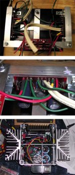
Many thanks to Brian and Meredith and Peter for putting this all together and the inspiration to give this a shot, and to everyone else that makes this board such a great place!
Here are a few pictures of the work in progress, I am waiting for the transformer and then I will build the chassis. I threw in a picture of a zen4 that is also in progress, quite a difference to say the least. Nothing beats the zip-tie to hold the toroid in place.
I am not exactly a master at this, but it keeps me out of trouble.
Attachments
Re: Build in progress
Nice work there, tick. I especially like your Zen's heatsinks. They look like they would be good for making a nice ~200W bridgeclone, if you were ever so inclined to do so.
Nice work there, tick. I especially like your Zen's heatsinks. They look like they would be good for making a nice ~200W bridgeclone, if you were ever so inclined to do so.
tick said:Many thanks to Brian and Meredith and Peter for putting this all together and the inspiration to give this a shot, and to everyone else that makes this board such a great place!
Here are a few pictures of the work in progress, I am waiting for the transformer and then I will build the chassis. I threw in a picture of a zen4 that is also in progress, quite a difference to say the least. Nothing beats the zip-tie to hold the toroid in place.
I am not exactly a master at this, but it keeps me out of trouble.
Re: Build in progress
Yes, no magnetic parts passing thru the donut hole.
dave
tick said:Nothing beats the zip-tie to hold the toroid in place.
Yes, no magnetic parts passing thru the donut hole.
dave
Is my GC dead?
Hi,
I'm using a centre-tapped transformer, with wiring
as described by Brian here:
http://www.diyaudio.com/forums/showthread.php?postid=359644#post359644
I wired up one channel last night, had a listen
and it was ok.
So I wired up the second channel this morning.
It was distorting badly and was heating up very quickly.
I shut things down and unsoldered the second
channel from the PS.
Now when I went back to the first channel, it too was
distorting and heating up.
When I measure the V+ and V- voltages on the PS,
they are at ~30 and ~-25 VDC respectively. Without
the GC board connected, the rails on the PS are equal.
I assume the LM3875TF's are dead. Does anyone have
any ideas on what might have happened. I'm like to
have some ideas before trying again with another
set of chips.
Thanks,
Dennis
What do you mean 25-30v DC out from PSU? If you measure it with V- and V+ and it bounce from 25-30 respectivly, then u should check ur psu. I had it jump like that, then I resoldier it. Now my error is within 0.1-.2 V different. I think u should check all the soldier joint and check for shorting...etc. LM3875 is really tough to kill ! 😀
LM3875 is really tough to kill ! 😀
welll (/me clears throat) not if you (/me clears throat again) accidentally switch V+ and V- (/me is ashamed). As i did with one of my clones some time ago...

ever seen a cap exploding? this is worse. except for the oil. ic's dont contain any. A nice spark and a tiiiiiiny little puff of smoke.
To be precise, I've killed 3 LM's, 2 of which weren;t my fault (entirely). One was ruined by me (see above).
The second one went up in smoke when my cat
 started playing with the speaker cables which (in a cascade of bad luck) caused the PSU to fall on the not-really finished amp case (which had fallen of my table first, of course). This caused a short circuit somewhere. First the amp went dead, then the fuse blew. This was right after the same cat tipped over my first cup of coffee of the day, of course.
The third one I killed with static electricity. A couple of days ago, the sun was shining, the sky was blue, it was a little cold, i was wearing a woollen sweater, i walked to my amp, touched it and TICK no more left channel. Apparently, the wire grounding the case had come loose and was pretty close to the feedback resistor.

o well, finally finished the complete amp. pics will be up soon.
Any suggestions for replacement capacitors...I have an extra gainclone pcb and want to buy caps..etc..if I buy at digikey...
The order is 22gpb i.e. 39.9774 USD before I even buy something!! 10GBP handling fee and 12GBP shipping what a rip off! Why do they even have GBP? I say kick them out of the EU. 😉
How about Nichicon 50V Low Impedance 105°C (PL type)
Part No. UPL1H152MHH6 at mouser.com
The order is 22gpb i.e. 39.9774 USD before I even buy something!! 10GBP handling fee and 12GBP shipping what a rip off! Why do they even have GBP? I say kick them out of the EU. 😉
How about Nichicon 50V Low Impedance 105°C (PL type)
Part No. UPL1H152MHH6 at mouser.com
www.partsconnexion.com charges very reasonable prices for shipping & handling to the netherlands and they're pretty fast too.
Hi Matjans,
They don't stock Panasonic or Nichicon in the right value.
The Black Gates are way above my budget...in the right value ;-)
Cheers,
Bas
They don't stock Panasonic or Nichicon in the right value.
The Black Gates are way above my budget...in the right value ;-)
Cheers,
Bas
www.acoustic-dimension.com is not very expensive with BG's.
Nichicon PL is not the finest sounding around, Panasonic FC is much better.
Nichicon PL is not the finest sounding around, Panasonic FC is much better.
- Status
- Not open for further replies.
- Home
- Amplifiers
- Chip Amps
- Gainclone building thread based on BrianGT's boards