Hi John
M44/7 one of the highest output MM cartridges, 11mVrms from monaural, 9.4 from stereo grooves @ 1kHz, 5cm/sec.
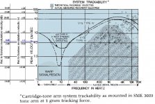
You can expect at least 20 dB (x10) higher output at mid frequencies from music in vinyl and even higher with good recordings at high frequencies (see first attachment)
The MM-MI output voltage (mV at 1kHz, 5cm/s) varied a lot among brands and models of the same brand.
AKG 0.95-1.65mV, Audio Technica 4.5-5mV, B&O 2.12mV, Goldring 5.5-6.5mV, Grado 2.5-5.5mV, Ortofon 2.0-6.0mV, Pickering 0.33-5.0mV, Shure 3.0-9.5mV, Sonus 4.0-5.0mV, Stanton 0.3-4.5mv, Technics 1.2-2.5mV. (data from 1984-1988 catalogues)
You may simulate various RIAA preamp schematics in Spice to study their overload characteristics.
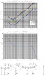
Second attachment are measured results from a split passive preamplifier (100 Ohm signal generator, 4k7 Ohms preamp load)
George
M44/7 one of the highest output MM cartridges, 11mVrms from monaural, 9.4 from stereo grooves @ 1kHz, 5cm/sec.
You can expect at least 20 dB (x10) higher output at mid frequencies from music in vinyl and even higher with good recordings at high frequencies (see first attachment)
The MM-MI output voltage (mV at 1kHz, 5cm/s) varied a lot among brands and models of the same brand.
AKG 0.95-1.65mV, Audio Technica 4.5-5mV, B&O 2.12mV, Goldring 5.5-6.5mV, Grado 2.5-5.5mV, Ortofon 2.0-6.0mV, Pickering 0.33-5.0mV, Shure 3.0-9.5mV, Sonus 4.0-5.0mV, Stanton 0.3-4.5mv, Technics 1.2-2.5mV. (data from 1984-1988 catalogues)
You may simulate various RIAA preamp schematics in Spice to study their overload characteristics.
Second attachment are measured results from a split passive preamplifier (100 Ohm signal generator, 4k7 Ohms preamp load)
George
Attachments

For this particular preamp, I want to figure out a way to keep the filters passive.
I’m sure it’s possible.
No reason to change the RIAA network at all, regardless.
Just the absolute and relative amounts of gain in the two op amps.
Hi Rayma,
Absolutely. The easiest way, as both you and Rogon pointed out, would be to lower the gain on one or both gain stages—starting with the first stage.
However, for flexibility, I want to maintain the usual ~40db gain.
I have lower output cartridges, and some lower gain amps and preamps I would like to use it with.
It is very likely that I could find the right balance in gain ratio to achieve this if I can determine which gain stage might be clipping.
The solution that appeals to me more, at this moment, is to increase the voltage swing capability of the gain stages. (Is that the correct way of putting it?)
I’m just wondering if this can be achieved with IC Op Amps.
Sorry, I realize this is a turn away from the thread title.
I promise to try adjusting the gain before doing anything more radical.
Regards,
John
Your first stage should be able to accept an input peak voltage of around 0.6V peak. This should be plenty.
Most op amps use up to 15V supplies, or slightly higher but not enough to make much difference.
That's an advantage of discrete circuitry.
If the first stage is overloading, try first stage 22dB (1.74k and 150R) and second stage 32dB (5.82k and 150R).
There will be a noise penalty, though. If the second stage is overloading, reverse the order.
Overall gain will remain the same, 34dB at 1kHz.
Last edited:
I will try your suggestion tomorrow. Thanks.
RE voltage swing: I also have some OPA604 which can be run at +/-24V.
Or what about something like the OPA552 which is designed to run on +/-30V?
I’m getting a bit ahead of myself, here, but this is the direction my thinking is going.
Regards,
John
RE voltage swing: I also have some OPA604 which can be run at +/-24V.
Or what about something like the OPA552 which is designed to run on +/-30V?
I’m getting a bit ahead of myself, here, but this is the direction my thinking is going.
Regards,
John
I would determine the precise problem first: whether there is excessive overloading, and if so, where it is.
At 1kHz, the peak cartridge output can be up to about 0.27V peak before overloading the output stage.
Overall 1kHz gain is x50 (34dB): 50 x 0.27Vpeak input = 13.5Vpeak (at output of second stage).
That overload would be around 27mVpeak input for low frequencies.
First stage can accept about 0.6Vpeak at any frequency from the cartridge before its output overloads.
First stage has gain of about x22 (27dB): 22 x 0.6Vpeak = 13.2Vpeak (at output of first stage before RIAA).
Last edited:
Problem seems to be fixed, but it is a bit perplexing.
I swapped out the opamps when I got home last night in an “eh, why not?” impulsive moment. 20 seconds worth of work, and I didn’t have to get out the soldering iron.
I put an OPA27 on the input and an AD797 on the output. No more clipping “crack” sound when the needle is lifted and the compression-like artifacts are gone. In fact, it sounds quite nice now.
So, I’m guessing that the cause(s) may be:
1- cold solder joint that was wiggled into better contact when the IC were swapped.
2- the Milmax 8dip sockets weren’t making proper contact previously.
3- one or more of the original opamps were damaged. (Less likely)
4- there is something about the OPA27/AD797 combo that works better in the given enviroment. (Less likely)
I will eventually explore gain ratio options, as the gain is a bit low anyway.
For now I’m happy to use it as is. If it acts up again, I’ll take the boards out and inspect them closely with a loop.
Thanks to everyone who took the time to respond.
Sorry it ended with such a fizzle.
Best regards,
John
Good work. Then I'd keep the TI circuit as shown in the data sheet.
If the gain is really too low, increase both stages equally, by 3dB or so each.
Could the original op amps have been "fakes"?
If the gain is really too low, increase both stages equally, by 3dB or so each.
Could the original op amps have been "fakes"?
I hope not! They came from either Digikey or Mouser. If they are getting fakes, we’re all doomed!
Best,
John
Best,
John
I used an OPA134 on the input, originally. No reason that shouldn’t have worked.
I think it must have been pilot error, somewhere.
I think it must have been pilot error, somewhere.
You can put the 75us compensation on the input by reducing the value of what "was" 47k -- if you know the "H" and "R" of the cartridge it's not difficult to make the adjustment. This both reduces the thermal noise component and militates against the clicks and pops! Inductance of the M44 is ~720mHPassive correction is fashionable, but technically bad.
Then, the 3180us and 318us compensation values can be determined from Lipshitz.
…one would be stuck to one cartridge, but I quite like the M44 on this deck. Expert Stylus makes a very nice “Extended Contact” nude elliptical for it—and for a reasonable price. Last time I checked it was a regularly stocked item, but that was when the styli were still in production by Shure. I read that a few radio stations used them.
Looking at it under a microscope it looks somewhat similar to a Geiger 2.
Looking at it under a microscope it looks somewhat similar to a Geiger 2.
Hi Jackinnj,You can put the 75us compensation on the input by reducing the value of what "was" 47k -- if you know the "H" and "R" of the cartridge it's not difficult to make the adjustment. This both reduces the thermal noise component and militates against the clicks and pops! Inductance of the M44 is ~720mH
Then, the 3180us and 318us compensation values can be determined from Lipshitz.
Thanks for your response!
I find this very interesting.
How do you calculate the load resistor? When I looked this up, I saw a few posts where you mention that it can be done, but no mention of the formula.
Shure M44-7:
650ohm
720mH (old Shure brochures state 650mH, so who knows)
Here is the model in my mind:
So, the parameters:
Cartridge resistance - Rc
Cartridge inductance- Lc
Cable capacitance- Ca
Load Resistor- Ra
75uS pole- Fc
Rc=650R
Lc= 720mH
Ca= ~60pF (per channel with my cable)
Fc= 2122Hz
From this I know how to calculate a simple LR Lowpass: Ra=2πLcFc
From the above this gives me ~9k6 for the load resistor
But how do the cartridge resistance "Rc" and cable capacitance "Ca" affect the equation?
Regards,
John
Last edited:
I've experimented a bit with this in LTspice simulations and by ear with a few different cartridges.
You mentioned your Ca (cable capacitance) is about 60pF per channel. That's really low! How did you do that? Short cables? What tonearm are you using?
My tonearm has about 30pF cable capacitance from headshell to tonearm base, and then my shortest, lowest capacitance tonearm cable has 85pF capacitance. My longer cable has about 110pF capacitance.
Using
Rc=650R
Lc= 720mH
Running this into a Hagerman Bugle simulated circuit with the standard 47k input load resistance and 100pF Ca (60pF + 40pF for tonearm wiring capacitance) I see a drooping response that's -5dB at 20kHz (referenced to 1kHz).

If I increase Ca to 200pF, this happens:

You can see the ever-so-slight bump up (resonance) centered around 7kHz. Response is now down -6dB at 20kHz.
Shure recommended a whopping 450pF for the M44-7, which yields a +2.5dB rise centered around 7.25kHz, and drops off to -9.5dB at 20kHz.
NB: The above are purely electrical responses. SPICE simulation can't factor in the mechanical response of the cartridge suspension, cantilever, tip resonance, etc. All that will influence the final results and could make things much different in real life from what you see above.
I'm sure the cartridge sounds nice, with a warm and full sound, with a lot of output. 9.5mV nominal is about twice (+6dB) what you'd get from most hi-fi cartridges. Is that what you desire? FYI... I have an M35X cartridge which I think is in-the-ballpark similar to M44-7...
You mentioned your Ca (cable capacitance) is about 60pF per channel. That's really low! How did you do that? Short cables? What tonearm are you using?
My tonearm has about 30pF cable capacitance from headshell to tonearm base, and then my shortest, lowest capacitance tonearm cable has 85pF capacitance. My longer cable has about 110pF capacitance.
Using
Rc=650R
Lc= 720mH
Running this into a Hagerman Bugle simulated circuit with the standard 47k input load resistance and 100pF Ca (60pF + 40pF for tonearm wiring capacitance) I see a drooping response that's -5dB at 20kHz (referenced to 1kHz).
If I increase Ca to 200pF, this happens:
You can see the ever-so-slight bump up (resonance) centered around 7kHz. Response is now down -6dB at 20kHz.
Shure recommended a whopping 450pF for the M44-7, which yields a +2.5dB rise centered around 7.25kHz, and drops off to -9.5dB at 20kHz.
NB: The above are purely electrical responses. SPICE simulation can't factor in the mechanical response of the cartridge suspension, cantilever, tip resonance, etc. All that will influence the final results and could make things much different in real life from what you see above.
I'm sure the cartridge sounds nice, with a warm and full sound, with a lot of output. 9.5mV nominal is about twice (+6dB) what you'd get from most hi-fi cartridges. Is that what you desire? FYI... I have an M35X cartridge which I think is in-the-ballpark similar to M44-7...
If your input load capacitance really is down around 100pF total, you might consider changing the input load resistor from the standard 47k ohms up to something like 68k. That should elevate the high frequency response enough to make it extend farther out towards 20kHz. I wonder if you'd notice more 'sparkle' and 'air' to the sound (please don't make fun of me for using audiophile cliché talk).
Since vinyl playback setups aren't standardized like digital, I believe you're free to play around until you find the combination of elements that pleases you most. Accuracy? You want accuracy? Go digital. Vinyl is now purely for fun (if this is the kind of thing that's fun for you...).
Since vinyl playback setups aren't standardized like digital, I believe you're free to play around until you find the combination of elements that pleases you most. Accuracy? You want accuracy? Go digital. Vinyl is now purely for fun (if this is the kind of thing that's fun for you...).
- Home
- Source & Line
- Analogue Source
- Gain distribution for passively equalized RIAA preamp