ITPhoenix: Thanks for the explantaion of what a state diagram is.
I'll do my best to explain to add to the other contributions, all good, just different ways of explaining the same behaviour.
It's common to split the analysis into DC and AC.
The DC signal at the JFET gate is close to 0 V.
The AC signal at the JFET gate is a low amplitude waveform, perhaps a few 100 microvolts (centred on the DC signal of 0V) that hopefully tracks the sound pressure variations on the diaphram.
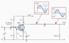
The DC signal at the JFET drain is somewhere between 0V and V+. It actual value depends on the JFET, V+ and the resistor value. It is biasing the JFET so that is in between being 'fully' On and 'fully' Off in a 'linear' region of operation. The current is always into the drain. The wanted signal signal (AC) can be viewed as a minor variation of the drain current.
The AC signal at the JFET drain will be a somewhat larger value of the signal at the gate. Only a few mV for an Electret capsule. Again depends to the JFET, the resistor, V+ and what the microphone output is connected to.
The AC signal at the Output (the end of the electrolytic capactor) will be the same as the signal at the JFET drain (into a high impedance). The DC signal will depend on what it's connected to.
The picture by godfrey shows when a resistor Rload is added the AC signal is unchanged but the DC level has changed from the DC Bias Voltage to 0 V.
The picture shows the signal having a large amplitude but in reality for an electret the signal is a few mV sitting on a DC bias Voltage of say a Volt or two depending on supply. The drain voltage will get nowhere near 0V or +Vcc.
I'll do my best to explain to add to the other contributions, all good, just different ways of explaining the same behaviour.
It's common to split the analysis into DC and AC.
The DC signal at the JFET gate is close to 0 V.
The AC signal at the JFET gate is a low amplitude waveform, perhaps a few 100 microvolts (centred on the DC signal of 0V) that hopefully tracks the sound pressure variations on the diaphram.
The DC signal at the JFET drain is somewhere between 0V and V+. It actual value depends on the JFET, V+ and the resistor value. It is biasing the JFET so that is in between being 'fully' On and 'fully' Off in a 'linear' region of operation. The current is always into the drain. The wanted signal signal (AC) can be viewed as a minor variation of the drain current.
The AC signal at the JFET drain will be a somewhat larger value of the signal at the gate. Only a few mV for an Electret capsule. Again depends to the JFET, the resistor, V+ and what the microphone output is connected to.
The AC signal at the Output (the end of the electrolytic capactor) will be the same as the signal at the JFET drain (into a high impedance). The DC signal will depend on what it's connected to.
The picture by godfrey shows when a resistor Rload is added the AC signal is unchanged but the DC level has changed from the DC Bias Voltage to 0 V.
The picture shows the signal having a large amplitude but in reality for an electret the signal is a few mV sitting on a DC bias Voltage of say a Volt or two depending on supply. The drain voltage will get nowhere near 0V or +Vcc.
A quite detailed analysis of parts involved in electret condenser button mics, including info of the typical internal jfet device 2SK596
electret microphones | Open Music Labs
Taking these for a test drive, my observations show following bias to the condenser itself, self bias arranged NPN's are very popular to amplify. But plenty of other variations abound.
Nearly 30 years ago I recall building many of these as the audio pick up part of simple FM transmitters, and the condenser could pick up amazing detail of sounds.
Back then, ..unsure if any better circuits are now around... probably🙂 ... but nevertheless great results were obtained with bias to the condenser from a 6v supply about 47k,(its other terminal ground ), then from that into a 22nf cap into the base of a BC547 the base then connecting to the collector with a 1meg- 2 meg resistor, its emitter ground and a 22k leading up from collector to V+ and 1uf from collector as audio out. if coupling on further to a second transistor (which was usually arranged as a tank circuit on its collector components ) for very rudimentary FM, ... a 100n was usually sufficient.
Cheers / Chris
Hope this helps...
(Mooly's already doing the thousand words, I'll add the picture 😀)
Excellent 😉
Thank you everyone for your steadfast interest in helping a rank beginner. It is apparent I must go back to the fundamentals and proceed without omitting anything. However, all the your contributions will be referenced as I go along.
DF96: I am definitely confused with AC/DC mixed circuits. They were always separate, or interfaced with "dry" contacts, in my experiences. A second thought about current reversal: This must be true since there is a common connection with the base, as transistors are polarity sensitive. See, I am having trouble understanding fundamental lessons.......... jumping ahead and misreading.
Famous Amos quote: "You have to start from where you are."
DF96: I am definitely confused with AC/DC mixed circuits. They were always separate, or interfaced with "dry" contacts, in my experiences. A second thought about current reversal: This must be true since there is a common connection with the base, as transistors are polarity sensitive. See, I am having trouble understanding fundamental lessons.......... jumping ahead and misreading.
Hi,
What experiences ? I have no idea what you are referring to.
With a positive supply and ground, current can only flow in one direction,
from positive to negative. There is a standing DC current through the FET,
and this gives a standing DC voltage across the load resistor which is also
the standing bias voltage across the capacitor so the output is referenced
to ground.
The capsule modulates the gate and hence the current through the FET.
This changes the current through the resistor, increasing and decreasing
it, but its still all flowing in the same direction. Its the capacitors stored
DC voltage that allows current reversal in the output, it does not occur
in the FET. You need to read up on single rail AC input/output coupling.
rgds, sreten.
sreten, My experiences involve mostly AC motor control, with electomechanical DC logic. If I needed to switch AC I bought a DC controlled TRIAC, if I needed to control the RPM of an AC motor I bought a VFD and programmed it accordingly.
Eureka, at one point I surmised the only way to get inversion was by the cap's discharge!
Now there are more posts above that I did not see. I cannot wait to take apart the zoom mic to see how they built it, and find out why the soundcard blew out. I did notice pinning of the sound level meter on audacity...... I was speaking directly into it 12 inches away...... not to mention experimenting with mic-boost in alsamixer.
Confusion about AC and DC is not uncommon. The problem is that it is difficult for us to help unless you can articulate the point of your confusion, but if you could do that it would (without our help) get you 80% of the way to resolving the issue anyway.
One thing to do is remember that 'time varying DC' can alternatively be regarded as 'constant DC + AC'. There have been arguments on here about whether DC means 'constant' or 'unidirectional'. Someone sticking rigidly to one definition is likely to be confused when talking to someone using the other definition, especially if they don't realise this is happening. My guess is that someone brought up in the world of electricity is likely to regard DC as unidirectional, but in electronics it is generally better to regard DC as constant (i.e. zero Hz frequency). Any change is AC (frequency non-zero).
One thing to do is remember that 'time varying DC' can alternatively be regarded as 'constant DC + AC'. There have been arguments on here about whether DC means 'constant' or 'unidirectional'. Someone sticking rigidly to one definition is likely to be confused when talking to someone using the other definition, especially if they don't realise this is happening. My guess is that someone brought up in the world of electricity is likely to regard DC as unidirectional, but in electronics it is generally better to regard DC as constant (i.e. zero Hz frequency). Any change is AC (frequency non-zero).
DF96: I originally viewed DC as a relatively constant voltage and current, except for inrush. Then we come to digital square waves riding on top or below the zero line, or half sinewave rectifiers. In my training, AC invaribly meant there were positive and negative components. In the case of the electret, I see a complex DC waveform. The element by itself cannot intinsically change polarity by design.
I see your point, one must think outside the box in electronics. I was an isolationist and no longer have that luxury. In the world of manufacturing we often hear, "I need that done now!" That also means it better work. Hence, the black box building syndrome.
Even now, I could as one respondent suggested, just use the electret trusting its output is AC. This could actually work, but I think it would be better to know precicely how things work if I am to start building and modifying preamps. I may need to know at some point how to center the waveform, or some other modification, when interfacing with the ADC.
Yes, if you were taught that AC necessarily involves a change of sign then I can understand your confusion. Part of the problem is that introductory courses have to simplify things for new learners, but then people latch on to the simplifications and assume they are the whole truth. Try to think in terms of frequency rather than direction.ITPhoenix said:In my training, AC invaribly meant there were positive and negative components. In the case of the electret, I see a complex DC waveform.
Not really, just need to think inside a different box. Regard your previous training as a helpful start but now potentially misleading. Later on, once you have learnt to think inside this new box you may begin to think outside it too.one must think outside the box in electronics
The output of an electret is probably a mix of AC and DC. The output of a transistor is always a mix of AC and DC.
Aha! The truth came out. The capacitive nature of the device must be the cause.The output of an electret is probably a mix of AC and DC.
Unless it is used as a switch?The output of a transistor is always a mix of AC and DC.
Thanks.
The output of a switching transistor could be considered pulsed/intermittent DC or a mix of DC and AC. Use whichever model best fits the situation, and makes analysis easiest. This is the art of engineering: pick the appropriate model.
Hello,
I would prefer to call a complex DC waveform a complex waveform that is the sum of a DC component that is fixed (doesn't change with time) with an AC component (does change with time) that hopefully follows the sound pressure level changes. The complex waveform may or may not change polarity it just depends on the relative levels of the DC and AC.
At the JFET input I think that the voltage does change polarity (relative to the JFET source) depending on JFET gate leakage setting the DC level and the sound pressure level and sensitivity setting the AC level though the levels are low.
At the JFET drain the voltage is always positive with the peak AC voltage always being much less than the DC level.
When a transitor is used as a switch the concept of splitting the waveform into DC and AC components isn't very useful. It's easiest to analyse each state, on and off, and the switching regions individually. It's still possible to calculate the waveform average to give the DC component and also to determine the AC component but then it gets complicated because are you measuring the peak to peak, the AC average or rms or something else.
Unless it is used as a switch?
Thanks.
Hi,
If its used as a switch it can't be being used as an amplifier.
Used as an amplifier it must be biased (or self biased in
the case of this FET) to a DC operating point between
the rails, ideally midway, but that is not likely here
unless the load resistor is matched to the FET.
I don't know what training you have, but understanding
capacitor AC coupled inputs and outputs, i.e. the capacitor
coupling prevents any DC coupling, is fundamental basics.
rgds, sreten.
- Status
- Not open for further replies.
- Home
- Amplifiers
- Solid State
- Fundamental Electret Operation