PMA said:Depends on YOUR design topology and skills.
Sorry. It is addressed to me your reply?
Fotios
Doing away with an output inductor if that is what the designer believes in can be accomplished by
Use high FT output devices
Keep the loop gain low or use none at all
If you believe that a bit (take your pick here at 20k 10dB? 20db? 30db?) of feedback is good, use of an output inductor is recommended
Use high FT output devices
Keep the loop gain low or use none at all
If you believe that a bit (take your pick here at 20k 10dB? 20db? 30db?) of feedback is good, use of an output inductor is recommended
Re: Time Out, Please!
Goood Summmmary, fotios 😉 😉
There are two Professors in Electronics that I regard very highly
when comes to amplifier facts, figures and designs:
1. Professor Matti Otala, Finland, see my topic here:
Amplifiers >Solid State >Matti Otala - An Amplifier Milestone. Dead or Alive
http://www.diyaudio.com/forums/showthread.php?threadid=125541
2. W. M. Leach, Jr, USA. Designer of Low Tim Amp & Leach SuperAmp etc. etc.
By the way,
his Diy audio website is well worth a visit.
In my next post I will you show his recommendation of Output Inductor
and how you easily can make your own.
It is for his Leach Amp. Known as the Low Tim amplifier
* TIM ... a sort of intermodulation distortion
Regards
Lineup - not a professor, yet, but from Sweden!!!! 😎
-----------------------
fotios said:Gentlemen, please do a break! All those who write is ENGLISH for me! You put me in doubt. What recommend finally all of you? To use or not inductor in the output of my amp? It is obvious that your views differ. It is also clear that exists - for some time, as well as in other threads too - a dispute between some members who have a higher knowledge level from us the common mortal. Thus, with the slightest opportunity, they exploit a simple query from a member, to start a new battle. This puts me into suspicions that something else exists in reality behind all this. From that I understand, "caesar148" who started this thread, he is confused at the moment. Or he is also playing the game from the start?
With humility
Fotios
Goood Summmmary, fotios 😉 😉
There are two Professors in Electronics that I regard very highly
when comes to amplifier facts, figures and designs:
1. Professor Matti Otala, Finland, see my topic here:
Amplifiers >Solid State >Matti Otala - An Amplifier Milestone. Dead or Alive
http://www.diyaudio.com/forums/showthread.php?threadid=125541
2. W. M. Leach, Jr, USA. Designer of Low Tim Amp & Leach SuperAmp etc. etc.
By the way,
his Diy audio website is well worth a visit.
In my next post I will you show his recommendation of Output Inductor
and how you easily can make your own.
It is for his Leach Amp. Known as the Low Tim amplifier
* TIM ... a sort of intermodulation distortion
Regards
Lineup - not a professor, yet, but from Sweden!!!! 😎
-----------------------
.
Curriculum Vitae, CV
W. Marshall Leach, Jr., Professor
Georgia Institute of Technology
School of Electrical & Computer Engineering
Atlanta, Georgia
Education
* B.S. in Electrical Engineering, 1962, University of South Carolina, Columbia
* M.S. in Electrical Engineering, 1964, University of South Carolina, Columbia
* Ph.D. in Electrical Engineering, 1972, Georgia Institute of Technology, Atlanta
etc.
etc.
etc.
Current Fields of Interest
Electromagnetic theory, audio, electroacoustics, electronic circuit design, instrumentation, low noise electronic design, and electromagnetic compatibility.
etc.
etc.
etc.
Honors and Awards
* Outstanding Teacher Award in Electrical Engineering, Eta Kappa Nu, 1973.
* Outstanding Teacher Award, Georgia Institute of Technology, 1975.
* Fellow Award, Audio Engineering Society, 1980.
* Outstanding Teacher Award in Electrical Engineering, Eta Kappa Nu, 1982.
* Engineer of the Year, Greater Atlanta Chapter, Georgia Society of Professional Engineers, 1983.
* Outstanding Senior Professor Award in Electrical Engineering, Eta Kappa Nu, 2002.
* Fellow Award, The Institute of Electrical and Electronics Engineers, 2005.
* Outstanding IEEE Student Branch Adviser Award, 2007.
* Richard M. Bass Outstanding Teacher Award in Electrical Engineering, Eta Kappa Nu, 2007.
etc.
etc.
etc.
http://users.ece.gatech.edu/~mleach/bio.html
.
hi.
This is some valuable info in my opinion.
For all those building thier own diy amplifiers.
Note:
The following image + quote is originally
from Professor in Electronics W. M. Leach, Jr
DIY audio website & with some other stuff:
http://users.ece.gatech.edu/~mleach/
Regars Lineup
This is some valuable info in my opinion.
For all those building thier own diy amplifiers.
Note:
The following image + quote is originally
from Professor in Electronics W. M. Leach, Jr
DIY audio website & with some other stuff:
http://users.ece.gatech.edu/~mleach/
Regars Lineup
An externally hosted image should be here but it was not working when we last tested it.
R49/L1 is a component that needs some assembly.
It's actually the
- R49 resistor with some
- 22 gauge solid wire wrapped around it 11 times.
The easiest way to do this is to take your length of wire, strip one end, and solder it to one side of the resistor.
Now wrap the wire tightly around the resistor 11 times (it will fit!) and mark the wire where it meets the other end of the resistor.
Unwind it, cut the wire just past that mark, and strip it.
Now re-wind it and solder it into place.
You may notice that D1, D2, D3, D4, Q18, Q19, Q20, Q21, R50, and C25 were not mentioned in my ordered list. That is because all of these components are not mounted on the PCB and their placement will be covered in the Assembly section.
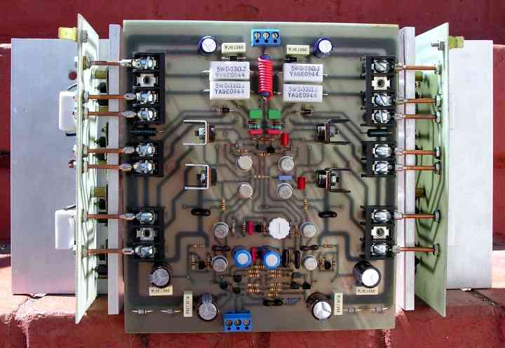
This is from
The Leach Superamp.
The second published amplifier by Professor W. M. Leach.
Notice the wire wounded output inductor.
It is is red colour in this assembled board.
Websource page:
http://users.ece.gatech.edu/~mleach/superamp/
The Leach Superamp.
The second published amplifier by Professor W. M. Leach.
Notice the wire wounded output inductor.
It is is red colour in this assembled board.
Websource page:
http://users.ece.gatech.edu/~mleach/superamp/
in greece ....
in a situation like that ( regarding this long post with so many opinions and theory ) we say
"÷áóáìå ôçí ìðáëá"
str8 translation is "we lost the ball"
in a situation like that ( regarding this long post with so many opinions and theory ) we say
"÷áóáìå ôçí ìðáëá"
str8 translation is "we lost the ball"
Re: Time Out, Please!
Try to analyse the facts by yourself and elaborate your own strong points of view. Reading some theory on amplifier design may help (feedback systems, open and closed loop gains, Nyquist stability criteria, etc...) You can improve your electronics knowledge in the process. Objectively there is nothing forcing you to be into a lower knowledge class.
Anyway, I think that there is enough evidence and consensus to support the fact that only amplifiers with properly sized RC and RL output networks can be stable with *any* load.
fotios said:Gentlemen, please do a break! All those who write is ENGLISH for me! You put me in doubt. What recommend finally all of you? To use or not inductor in the output of my amp? It is obvious that your views differ. It is also clear that exists - for some time, as well as in other threads too - a dispute between some members who have a higher knowledge level from us the common mortal. Thus, with the slightest opportunity, they exploit a simple query from a member, to start a new battle. This puts me into suspicions that something else exists in reality behind all this. From that I understand, "caesar148" who started this thread, he is confused at the moment. Or he is also playing the game from the start?
With humility
Fotios
Try to analyse the facts by yourself and elaborate your own strong points of view. Reading some theory on amplifier design may help (feedback systems, open and closed loop gains, Nyquist stability criteria, etc...) You can improve your electronics knowledge in the process. Objectively there is nothing forcing you to be into a lower knowledge class.
Anyway, I think that there is enough evidence and consensus to support the fact that only amplifiers with properly sized RC and RL output networks can be stable with *any* load.
After all that...🙂...I hope you are still with us, Caesar148.caesar148 said:Thanks to all who replied. Okay, I am beginning to understand better now. The inductor is to prevent amplifier oscillation when driving "difficult" loads that have high capacitance.
I would conclude that amplifiers with small or no feedback would be less susceptable to such speaker load and could do away with it.
Anyone know what a recommended value of inductance it should be?
1) There is no right answer...it depends on the amp. Without getting really complicated, all you can do is take reasonable precautions.
As a general solution, I would recomend an inductor between 1uH and 2uH in parallel with a 10 ohm resistor.
If you would like to get really complicated about it then please ask...probably best to send me a private message, though. 😉
2) Me, Christer, John Curl, Bob Cordell and others are talking about very subtle difference in sound quality, with or without an inductor. Don't worry about it unless you are striving to make a really high-end amplifier.
3) Low or no global feedback designs tend to be more load tolerant. Not always the case as some have pointed out. Indeed, there is no such thing as an amplifer that doesn't use some species of feedback. There is no real harm in using the inductor/resistor anyhow, so you might as well use it in all cases.
4) Try not to get to confused by all this Zobel chatter. What is done in an audio amp is only a crude approximation to Zobel's theories. The term "Zobel network" is not being used properly - it's just a convenient jargon. You can't make a proper network because the speaker and speaker cables have a variable impedance.
5) The basic ideas are fairly simple. At low frequencies you want the amp to drive the speaker, to "see" the speaker impedance. Above the audio band you want the amp to "see" a constant, resistive load instead of the speaker and speaker cable. This is because the impedance of the speaker and cable can cause big phase shifts at frequencies in the MHz region. Some amps feedback loops are still active at these high frequencies and they can become unstable.
When designing, you choose the high frequency resistance you want the amp to see. 10-ohms is typical (in the case of the NS circuit that Lineup shows, it is 2.7 ohms). You put this resistance in series with a cap, typically 220nF, from the amp out to ground. To isolate the speaker/cable at high f you put a series inductor of 1uH or 2uH between the amp output and the speaker/cable. The inductor has a resistor in parallel to damp out potential resonances with any capacitance in the speaker. The f where the impedance changes from speaker to resistor is typically in the 100kHz or so region.
Zobel
Hi Glen,
I disagree with your disagreement. 🙂
Frankly speaking, I don't care who designed that NS Zobel thing, Thiele or even God. That network is ill designed, because at HF, the impedance drops from 8 to ~2.4 Ohm. Maybe others think it's a good idea, but I don't like at all. Also have a look at the step response.
Without consensus about the duties of a Zobel network, I'm afraid that a further discussion becomes rather difficult.
So let me point out what I think a Zobel network should and not should do.
1. Protecting the amp from HF ingress.
2. Protecting the amp from abuse, like a capacitive load or no load at all (i.e. the speaker outlet simply left open).
3. A constant and resistive impedance (seen by the amp) if the network is properly terminated, that is, also by a constant and resistive impedance, equal to the nominal impedance.
4. A minimal impact on frequency and step response, as well as distortion and damping factor.
5. I should NOT correct a deviation from the nominal speaker impedance, in particular at HF.
The latter belongs to the responsibility of loud speaker manufacturer. Happily, some decent manufacturers do this already. So putting another 'HF terminator' inside the amp lowers the impedance unnecessary and should be avoided.
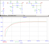
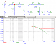
Coming back to the NS Zobel vs my version (schematics below), I simulated them and it appeared that the onset of frequency roll-off of my version happens at a two times higher frequency. Also the step response looks far better (green curve), i.e. faster and without that ugly kink.
One more thing regarding RFI: Analoguous to Bob Cordell's proposal to put a cap (plus resistor) right at the input terminals, I think it's equally beneficial to put the Zobel cap right at the output terminals.
Cheers,
Edmond.
G.Kleinschmidt said:I disagree. I've got some Neville Thiele articles where he describes the component values for a couple of load isolations/HF terminating networks designed to present a constant (with frequency) load impedance to the amplifier for both 4 and 8 ohms. One is just as the NS design.....
Hi Glen,
I disagree with your disagreement. 🙂
Frankly speaking, I don't care who designed that NS Zobel thing, Thiele or even God. That network is ill designed, because at HF, the impedance drops from 8 to ~2.4 Ohm. Maybe others think it's a good idea, but I don't like at all. Also have a look at the step response.
The only thing the output network has to do IMHO is to isolate any capacitive load to a sufficient degree with a well dampened inductor and provide a low impedance termination at HF. Works well for me and the squarewave response is infinitely better too! 😀
Cheers,
Glen
Without consensus about the duties of a Zobel network, I'm afraid that a further discussion becomes rather difficult.
So let me point out what I think a Zobel network should and not should do.
1. Protecting the amp from HF ingress.
2. Protecting the amp from abuse, like a capacitive load or no load at all (i.e. the speaker outlet simply left open).
3. A constant and resistive impedance (seen by the amp) if the network is properly terminated, that is, also by a constant and resistive impedance, equal to the nominal impedance.
4. A minimal impact on frequency and step response, as well as distortion and damping factor.
5. I should NOT correct a deviation from the nominal speaker impedance, in particular at HF.
The latter belongs to the responsibility of loud speaker manufacturer. Happily, some decent manufacturers do this already. So putting another 'HF terminator' inside the amp lowers the impedance unnecessary and should be avoided.
Coming back to the NS Zobel vs my version (schematics below), I simulated them and it appeared that the onset of frequency roll-off of my version happens at a two times higher frequency. Also the step response looks far better (green curve), i.e. faster and without that ugly kink.
One more thing regarding RFI: Analoguous to Bob Cordell's proposal to put a cap (plus resistor) right at the input terminals, I think it's equally beneficial to put the Zobel cap right at the output terminals.
Cheers,
Edmond.
Attachments
I think traderbam has summarized the spirit of the thread, including the for and against, in an excellent way.
Moderators, I propose you close this thread now, since it covers both the for and against in a concise manner. Lets try to avoid the situation where we slide into a for and against slinging match
Moderators, I propose you close this thread now, since it covers both the for and against in a concise manner. Lets try to avoid the situation where we slide into a for and against slinging match
face it people
95% of comercial amplifiers include inductors ....there is got to be reason for it .....
95% of comercial amplifiers include inductors ....there is got to be reason for it .....
Re: Zobel
Looking at these 5 points I can see that you obviously don't really disagree with my disagreement that much.
Points 3 and 4 are in conflict. I think it is a waste of time attempting to design the output network to provide an "ideal" resistive "impedance" to the amplifier because the huge deviations in the impedance of most loudspeakers. I use Nevile Thiele's (and some varaitions of) networks, but with modified component values for this reason. What do you think Nevile's 14uH inductor does for damping factor and transient response into capacitive loads?
BTW, I haven't forgotten about that Philips speaker article and if I come across my Nevile Thiele articles in the meanwhile also, I'll scan them too.
Cheers,
Glen
Edmond Stuart said:
Without consensus about the duties of a Zobel network, I'm afraid that a further discussion becomes rather difficult.
So let me point out what I think a Zobel network should and not should do.
1. Protecting the amp from HF ingress.
2. Protecting the amp from abuse, like a capacitive load or no load at all (i.e. the speaker outlet simply left open).
3. A constant and resistive impedance (seen by the amp) if the network is properly terminated, that is, also by a constant and resistive impedance, equal to the nominal impedance.
4. A minimal impact on frequency and step response, as well as distortion and damping factor.
5. I should NOT correct a deviation from the nominal speaker impedance, in particular at HF.
Looking at these 5 points I can see that you obviously don't really disagree with my disagreement that much.
Points 3 and 4 are in conflict. I think it is a waste of time attempting to design the output network to provide an "ideal" resistive "impedance" to the amplifier because the huge deviations in the impedance of most loudspeakers. I use Nevile Thiele's (and some varaitions of) networks, but with modified component values for this reason. What do you think Nevile's 14uH inductor does for damping factor and transient response into capacitive loads?
BTW, I haven't forgotten about that Philips speaker article and if I come across my Nevile Thiele articles in the meanwhile also, I'll scan them too.
Cheers,
Glen
Zobel or not to Zobel
Hi Glen,
And what about that NS Zoebel thing? Do you still believe it's correct?
As for point 3, I know that the amp output will never see a pure resistive and constant load. I'm only saying that IF the output of the Zobel network is terminated with the nominal load, then the input should reveal the same impedance. Just see it as a design rule and not as a real situation.
Regarding Nevile's 14uH inductor, I think even I can hear such huge coil. I wouldn't recommend it.
Thx in advance for the article.
Cheers,
Edmond.
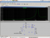
The cap directly on the output should be good for RF filtering but I see one problem: When the output is shorted at the other end of a short cable. The amplifier will see an impedance peak, see attachment. The plot shows the impedance as seen from the source.
(Yes that is LTSpice running in wine)
(Yes that is LTSpice running in wine)
Attachments
megajocke said:The cap directly on the output should be good for RF filtering but I see one problem: When the output is shorted at the other end of a short cable. The amplifier will see an impedance peak, see attachment. The plot shows the impedance as seen from the source.
(Yes that is LTSpice running in wine)
Hi MJ,
In that case we need an additional RC at the input side of the Zobel network. However, have we to take into account all possible forms of abuse? The more so as such short circuit condition should have to disconnect the amp from the load.
Cheers,
Edmond.
Domo arigato.Bonsai said:I think traderbam has summarized the spirit of the thread, including the for and against, in an excellent way.
Zobel & RFI
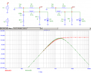
And here is a relative comparison of the capabilities to block RFI ingress of the NS (red) vs my version (green) of that Zobel thing (notice: these two versions use the same inductance).
Clearly, above a few MHz, that NS Zobel network does nothing. So I insist that most people are blindly and mindlessly copying existing schematics and haven't the faintest idea what they are doing.
Attachments
Edmond, how many amps still have 1 mOhm output Z at those frequencies? I think the usual explanation is that the output Z will be much higher than the Z of the Zobel at HF. Still, you have a point, I think.
Zobel & RFI
Hi Christer,
I'm afraid you missed my point point. I was talking about the relative performance of the two circuits. It doesn't matter if Zo of the output stage is 1, 10 or even 100 mOhm. Also, I was even looking at the wrong node (see new picture: out1 and out2). Even that doesn't matter. Anyhow, according my new sim, the NS version appears to be still inferior.
Cheers,
Edmond.
Christer said:Edmond, how many amps still have 1 mOhm output Z at those frequencies? I think the usual explanation is that the output Z will be much higher than the Z of the Zobel at HF. Still, you have a point, I think.
Hi Christer,
I'm afraid you missed my point point. I was talking about the relative performance of the two circuits. It doesn't matter if Zo of the output stage is 1, 10 or even 100 mOhm. Also, I was even looking at the wrong node (see new picture: out1 and out2). Even that doesn't matter. Anyhow, according my new sim, the NS version appears to be still inferior.
Cheers,
Edmond.
Attachments
- Home
- Amplifiers
- Solid State
- Function of Output Inductor