john curl said:Please talk to me over the phone before making opinion. I have done the research and published it.
John;
I did not mean that you should suspect a corrector. I would suspect a corrector in such case.
Sorry for confusing, you know well that English is not my native language.
John, maybe I misunderstood something, or got lost in the thread. If your rule of thumb was just to have more than a modest 10 V/us for 100 W output, then there is nothing to fuzz about. I got the impression you advocated much much higher values always, whatever amp we are talking about. My point then was that it should reasonably depend on the particular topology and implementation what the minimum requirement is.
If there was such a thing as a perfect amp, but it would clip at 100W and had only a slew rate of 10V/us, it would just squeek by, with most audio sources. However, it could still slew under some conditions, especially with an Ortofon moving coil cartridge, amplified directly without transformer to the power amplifier. In all other cases, where the amp was not perfect, 50V/us would be better.
How about music slew rate? Or better, how about tweeter slew rate? Or even better, how about air slew rate?
You can compress air as fast as you want, but when pressure is no longer applied, air expands at a somewhat slow rate. This is one of the major sources of 2nd order distortion in speakers. You can easily get 10% 2nd order THD at high SPL.
BTW: Is anybody capable of hearing transient errors lasting only a few microseconds? I can't. This is well above ultrasound.
You can compress air as fast as you want, but when pressure is no longer applied, air expands at a somewhat slow rate.
Really? Say I record a perfect sine, play it via speaker and record it again - all using perfect distortionfree equipment - I get a hugely distorted signal after, say, 10 times doing that at high SPL?
If that would be correct, one cannot even reproduce a perfect sine at all, since its reproduction would always be distorted. This would necessarily lead speaker distortion tests ad absurdum - even with perfect distortionfree transducers.
I'm sceptical - do you have some measured data on this?
All the best, Hannes
EDIT: thinking a bit more about it, it is obvious that only waves with compression velocities larger than the speed of sound are prone to this kind of distortion. A rough calculation gives me at least 30kHz as threshold (300m/s speed of sound, 1cm cone excursion).
compression and expansion of air are similar to the limitations that apply to a single ended ClassA stage.
Both exhibit distortion.
Both exhibit distortion.
Sr
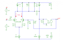
Hi John,
I like to add the results of a quick sim of the most common power amp topology, comprising a LPT, followed by a current mirror, VAS+compensation cap and an EF output stage. My purpose was to see if there is a relation between slew rate and harmonic distortion in real amplifiers (do you listen Brian?). So I manipulated some component values to get a SR of 8.8, 19.3 and 41.1V/us respectively.
Since the SR (in this case) is determined by the tail current and the value of the compensation cap, I've simulated this amp with three different caps: 220pF, 100pF and 47pF, and keeping the tail current constant. To get a fair comparison, I've also kept all other parameters at the same value, including the unity gain frequency of NFB loop, i.e. at 1MHz (practical values lie invariably between 0.5 and 2MHz, so 1MHz is quite reasonable, I think). Therefore I had to adjust the OL gain by trimming the emitter resistors of the LTP, in order to keep Fu of the NFB loop at 1MHz.
THD is simulated at 20kHz and 1Vpk input. Here are the results:
Cc (pF) ..... RE (Ohm) ..... SR (V/us) .... THD (ppm)
220 ........... 0 ................. 8.8 ............ 303
100p ........ 29 ................ 19.3 ........... 25.7
47p .......... 91 ................ 41.1 ........... 2.6
Cheers,
Edmond.
john curl said:In practice, you need MORE than 10V/us, even with expensive designs. John Meyer and I measured this for an audio magazine in 1977. We tested 4 power amps: Phase Linear 400, Audio Research D 100, Theshold (I think) and an Electroresearch power amp.
We found that 2 units passed TIM 30, with a nominal output that was below 100W, and 2 units did NOT pass. The Threshold and the Electroresearch passed, and the other 2 units failed. What the other 2 units had in common was a slew-rate that was 11V/us or less. When you see the distortion, even with 2 very different designs, it becomes obvious that 10V/us is really impractical for an IDEAL design. Now, I know that many IC power op amps are not faster than this because of cost of manufacture. OK, but don't expect perfection for every audio playback situation, with only 10V/us slew rate.
Hi John,
I like to add the results of a quick sim of the most common power amp topology, comprising a LPT, followed by a current mirror, VAS+compensation cap and an EF output stage. My purpose was to see if there is a relation between slew rate and harmonic distortion in real amplifiers (do you listen Brian?). So I manipulated some component values to get a SR of 8.8, 19.3 and 41.1V/us respectively.
Since the SR (in this case) is determined by the tail current and the value of the compensation cap, I've simulated this amp with three different caps: 220pF, 100pF and 47pF, and keeping the tail current constant. To get a fair comparison, I've also kept all other parameters at the same value, including the unity gain frequency of NFB loop, i.e. at 1MHz (practical values lie invariably between 0.5 and 2MHz, so 1MHz is quite reasonable, I think). Therefore I had to adjust the OL gain by trimming the emitter resistors of the LTP, in order to keep Fu of the NFB loop at 1MHz.
THD is simulated at 20kHz and 1Vpk input. Here are the results:
Cc (pF) ..... RE (Ohm) ..... SR (V/us) .... THD (ppm)
220 ........... 0 ................. 8.8 ............ 303
100p ........ 29 ................ 19.3 ........... 25.7
47p .......... 91 ................ 41.1 ........... 2.6
Cheers,
Edmond.
Attachments
I wrote:
Would you quantify the benefit to performance that your proposal delivers?
Edmond wrote:
I have done that already, but you seem totally deaf to any rational argument.
No you have not. Where have you talked about the amplifier performance measure(s) that will be improved by your shunt cap proposal and by how much you expect them to be improved?
Standard engineering question.
Hint. This is not a simple question to answer. You have to consider what the EMI rejection needs to be (amplitude and frequency range): what EMI environment the amp is designed to operate in, how good a receiver is a speaker cable, what the transmission function is bewteen cable and amp output before the filter, how big this EMI signal is compared to the RF generated by the amp itself, and whether the speaker cable will be the dominant source of EMI compared with signal inputs, mains input and free air ingress through the case material or gaps in the case. Crucially, what important performance parameters of an amp will be affected, and whether they will be affected in a significant way.
Brian,
I have clearly shown that my circuit does attenuate RF ingress, while the other circuit does almost nothing. It's just a relative comparison. That's all.
I have clearly shown that my circuit does attenuate RF ingress, while the other circuit does almost nothing. It's just a relative comparison. That's all.
Free papers on air non-linearity are hard to find. Googling for ' air compression rarefaction distortion ' gives a couple of free results.
This is a quote from Nelson Pass:
"Its asymmetry is similar to the compression / rarefaction characteristic of air, where for a given displacement slightly higher pressure is observed on a positive (compression) than on a negative (rarefaction). Air itself is observed to be a single-ended medium, where the pressure can become very high, but never go below 0. The harmonic distortion of such a medium is second harmonic, the least offensive variety."
This deals with air distortion due to compression at low frequencies:
http://www.lungster.com/l/speakers/BassListArchive.shtml
There are essentially two problems with air:
- Not all the energy provided to the air during compression is either radiated as a sound wave or returned to the diaphragm during rarefaction. Some energy is just lost as heat during the process. This phenomena is compression-rate dependent (similar to slew rate).
- Equal positive and negative volume changes don't result in equal positive and negative SPL changes. The higher the SPL change becomes in comparision with ambient pressure, the higher the distortion becomes.
Ambient pressure is approx. 100.000 Pascals while, 130dB SPL is approx. +/-100 Pascals.
I find that kind of subjects far more interesting than class AB amplifier design, where everything has been invented and improved ad infinitum.
Re: Sr
doubling Cdom (Cc), increases distortion by a factor of 10!
But, is it a Cdom loading effect or a slew effect or an LTP linearity effect or something else?
Illuminating.Edmond Stuart said:To get a fair comparison, I've also kept all other parameters at the same value, including the unity gain frequency of NFB loop, i.e. at 1MHz..........Therefore I had to adjust the OL gain by trimming the emitter resistors of the LTP, in order to keep Fu of the NFB loop at 1MHz.
THD is simulated at 20kHz and 1Vpk input. Here are the results:
Cc (pF) ..... RE (Ohm) ..... SR (V/us) .... THD (ppm)
220 ........... 0 ................. 8.8 ............ 303
100p ........ 29 ................ 19.3 ........... 25.7
47p .......... 91 ................ 41.1 ........... 2.6
doubling Cdom (Cc), increases distortion by a factor of 10!
But, is it a Cdom loading effect or a slew effect or an LTP linearity effect or something else?
And don't forget than even the original sound from an instrument is subject to air-compression distorsion. Compressing it again, even further when reproducing will cause more distorsion, though.
The sound of the original instrument is not distortion.Christer said:And don't forget than even the original sound from an instrument is subject to air-compression distorsion. Compressing it again, even further when reproducing will cause more distorsion, though.
That is real life. That is what we strive to reproduce with High Fidelity.
Not HiFi in it's modern usage.
AndrewT said:
The sound of the original instrument is not distortion.
That is real life. That is what we strive to reproduce with High Fidelity.
Not HiFi in it's modern usage.
Yes, I know distorsion may be semantically wrong here. I just wanted to point out that the effect itself already arise in the original, contrary to (most) other types of distorsion. That is, it is not entirely an artifact.
well, if you want to get technical... we are just a small distortion in the space time continuim.
Above link deals entirely with thermodynamics and it even explains the concept of an adiabatic process wrongly.
Nevertheless the ideal gas law proves you right, that is, that a compression increases the temperature of the compressed gas.
However, the real question is - and that is entirely missing - to which extent this effect is of any significance.
Let's do another rough approximation: ideal gas law states pV=nRT (p pressure, V volume, R gas constant, T temperature). If we label the initial state with a 1 and the final state with a 2
p1 V=nR T1
p2 V=nR T2
where I assume constant volume and particle densities. Dividing these 2 eqations yields simply
p2/p1=T2/T1
so a pressure change of 100 Pascals ontop of the 100.000 Pascals ambient pressure gives a relative temperature change of 1/1000.
I didn't bother to lookup the according change in speed of sound, it just does not appear to be a significant process. Even temperature changes within the same room are much larger.
Have fun, Hannes
most electronics designers look for far deeper than -60dB effects.h_a said:......so a pressure change of 100 Pascals ontop of the 100.000 Pascals ambient pressure gives a relative temperature change of 1/1000.....
Eva said:Ambient pressure is approx. 100.000 Pascals while, 130dB SPL is approx. +/-100 Pascals.
I now see I misread Eva's post due to the Continental use of the "." as the thousands separator.h_a said:so a pressure change of 100 Pascals ontop of the 100.000 Pascals ambient pressure gives a relative temperature change of 1/1000.
How do we solve this problem?
Y*10^x, or YEx or instructions in a Wiki, or a sticky thread. What?
Does this mean 150dB SPL at the driver is equivalent to -40db pressure change?
Well, Andrew, you assume that speed of sound is linearly dependant on temperature which is not correct. It has square root dependance, so a 0.02 °C change yields a relative change in speed of sound of 1.0005 and that is already rounded up.
All the best, Hannes
EDIT: from Evas data I assumed the point is indeed a thousands separator, however I didn't check the values per se.
EDIT2: I'm sorry if I cause confusion, above figure uses the point as comma, so just for sake of clarity 1,0005. Seems to be indeed -66dB. Anyway these are rough figures estimated on a piece of scrap paper, I'm sure by looking more closely one can cut that down further. If this is considered significant, then the spatial changes in room temperature in an average room would be more important.
Re: Re: Sr
Hi Andrew,
It's both a Cdom loading effect, in the sense that the input stage has to deliver more current, and of course the nonlinearity of the input stage itself.
Cheers,
Edmond.
AndrewT said:Illuminating.
doubling Cdom (Cc), increases distortion by a factor of 10!
But, is it a Cdom loading effect or a slew effect or an LTP linearity effect or something else?
Hi Andrew,
It's both a Cdom loading effect, in the sense that the input stage has to deliver more current, and of course the nonlinearity of the input stage itself.
Cheers,
Edmond.
- Home
- Amplifiers
- Solid State
- Function of Output Inductor