I am probably unqualified but ......
Split the 1k resistor to two 500 ohms to ground. Split the 1 nF into two 500 pF caps to ground. It could be that the negative feed back appears largly as a common mode signal at very high frequencies and has no real ground refererence. Some preamps do not like driving capacitive loads so put series resistors from the input to the 500pF caps. Another explanation might be slew rate limitations in the amps.........
Split the 1k resistor to two 500 ohms to ground. Split the 1 nF into two 500 pF caps to ground. It could be that the negative feed back appears largly as a common mode signal at very high frequencies and has no real ground refererence. Some preamps do not like driving capacitive loads so put series resistors from the input to the 500pF caps. Another explanation might be slew rate limitations in the amps.........
Not Quite
Op amp circuit not power amps. The power amps will be harder to get stable than the op amp circuit.
Op amp circuit not power amps. The power amps will be harder to get stable than the op amp circuit.

Try Zobel circuit accross speaker terminals (RC series circuit, R=5 Ohm, C=15nF approx.), solder it directly to amp output speaker terminals. Small inductance of some 20uH // 1 Ohm resistor in series with wire to live speaker terminal might help, too.
PMA said:Try Zobel circuit accross speaker terminals (RC series circuit, R=5 Ohm, C=15nF approx.), solder it directly to amp output speaker terminals. Small inductance of some 20uH // 1 Ohm resistor in series with wire to live speaker terminal might help, too.
Actually, the zobel network(s) and inductors, (~1uH each), are contained within each power amp.....
PMA said:You might also like to connect resistors of some 100 Ohm in series with input 47uF capacitors.
...previously tried 1K....didn't help....

Re: Not Quite
I'll try splitting the input filter cap....but first will remove it altogether..make sure it works...otherwise make a mess of pcb's...
...no..each power amp slews at over 45V/uS, (more or less symmetrically), and when used in the traditional configuration, they are unconditionaly stable, giving ~350 Watts into 2 ohms...
...As you may have noticed, this particular topology is the standard input stage on discrete instrumentation amps....see
http://users.ece.gatech.edu/~mleach/ece4435/chap01.pdf
http://www.analog.com/UploadedFiles/Associated_Docs/42329367appguide.pdf
http://www.analog.com/UploadedFiles/Application_Notes/442106604AN244.pdf
http://www.analog.com/UploadedFiles/Application_Notes/487451449AN589.pdf
http://www.analog.com/UploadedFiles/Application_Notes/63300941AN245.pdf
On the face of it, there shouldn't be any problem getting it to work with lab. dummy load....(before connecting it to 'speaker of course)....after all...a power amp. is merely butch op. amp....no?
Fred Dieckmann said:Split the 1k resistor to two 500 ohms to ground. Split the 1 nF into two 500 pF caps to ground. It could be that the negative feed back appears largly as a common mode signal at very high frequencies and has no real ground refererence. Some preamps do not like driving capacitive loads so put series resistors from the input to the 500pF caps. Another explanation might be slew rate limitations in the amps.........
I'll try splitting the input filter cap....but first will remove it altogether..make sure it works...otherwise make a mess of pcb's...
...no..each power amp slews at over 45V/uS, (more or less symmetrically), and when used in the traditional configuration, they are unconditionaly stable, giving ~350 Watts into 2 ohms...
Fred Dieckmann said:Op amp circuit not power amps. The power amps will be harder to get stable than the op amp circuit.
...As you may have noticed, this particular topology is the standard input stage on discrete instrumentation amps....see
http://users.ece.gatech.edu/~mleach/ece4435/chap01.pdf
http://www.analog.com/UploadedFiles/Associated_Docs/42329367appguide.pdf
http://www.analog.com/UploadedFiles/Application_Notes/442106604AN244.pdf
http://www.analog.com/UploadedFiles/Application_Notes/487451449AN589.pdf
http://www.analog.com/UploadedFiles/Application_Notes/63300941AN245.pdf
On the face of it, there shouldn't be any problem getting it to work with lab. dummy load....(before connecting it to 'speaker of course)....after all...a power amp. is merely butch op. amp....no?
tschrama said:Some resistance form inverting inputs to ground maybe?
Regards,
Thijs
Hhhmmmm interesting idea.....
 ....would have to be matched....
Bridging?
Hi mikek.
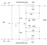
Fom the picture above I have a conclusion that you want to bridge
these amps.Why don't you choose the "conventional"method of
bridging amps? There are many good ways to do that.
Or this is a experiment?
Regards friend.
Hi mikek.
Fom the picture above I have a conclusion that you want to bridge
these amps.Why don't you choose the "conventional"method of
bridging amps?
There are many good ways to do that.Or this is a experiment?
Regards friend.
Michael,
what happens when you create dominant pole by a capacitor placed in parallel with 10k feedback resistor, starting from slower response and trying to get to faster ...
Pavel
what happens when you create dominant pole by a capacitor placed in parallel with 10k feedback resistor, starting from slower response and trying to get to faster ...
Pavel
Re: I am probably unqualified but ......
splitting the 1k resistor as you've described will result in both outputs being in phase....not 'differential' any more...🙂
Fred Dieckmann said:Split the 1k resistor to two 500 ohms to ground. Split the 1 nF into two 500 pF caps to ground.
splitting the 1k resistor as you've described will result in both outputs being in phase....not 'differential' any more...🙂
Hello mikek,
If you reduce this circuit to a system block diagram, letting B be the feedback factor of a single loop and Z2 and Z1 be the feedback impedances (where Z2 is the impedance from output back to inverting input), you'll find that for one of the loops,
B = (Z1+Z2)/(Z1+2*Z2)
For simplicity, let's ignore the 100 Ohm resistor and series capacitor. Then Z1 = 1000 and Z2 = 10k. So your feedback factor is really 11000/21000, roughly 0.5. This means your amp must be stable with a closed-loop gain of 2. I suspect that for single-ended operation your stability was achieved at a higher closed-loop gain. So I think the problem you're having is one of more loop gain than in the single-ended configuration. So I suspect you'll need to adjust your frequency compensation accordingly.
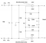
oops...
here are the output inductors and zobel network as they should have appeared in the first figure....sorry about that....cheers.
PMA said:Try Zobel circuit accross speaker terminals (RC series circuit, R=5 Ohm, C=15nF approx.), solder it directly to amp output speaker terminals. Small inductance of some 20uH // 1 Ohm resistor in series with wire to live speaker terminal might help, too.
here are the output inductors and zobel network as they should have appeared in the first figure....sorry about that....cheers.
Attachments
Re: Bridging?
Hi hightec, 🙂
'bridge' it is.....however this circuit is often used in op amp. circuits, and looks irresistibly elegant..........'conventional' methods don't appeal to me much........like to experiment..🙂
However, any ideas are most welcome...conventional...or not....🙂
HighTec said:Hi mikek.
Fom the picture above I have a conclusion that you want to bridge
these amps.Why don't you choose the "conventional"method of
bridging amps?
Or this is a experiment?
Regards friend.
Hi hightec, 🙂
'bridge' it is.....however this circuit is often used in op amp. circuits, and looks irresistibly elegant..........'conventional' methods don't appeal to me much........like to experiment..🙂
However, any ideas are most welcome...conventional...or not....🙂
"splitting the 1k resistor as you've described will result in both outputs being in phase....not 'differential' any more..."
Both outputs are in phase now! Each half of the circuit is a noninverting amplifier. The circuit has to be driven by two indentical signals that are 180 degrees out of phase. As a thought experiment, split the 1K resistor into two 500 ohm resistors and don't connect the junction to ground. What is the signal voltage at this point? Driving a speaker balanced with no connection to ground will result in rejection of common mode input signals, so you real don't have an advantage in common mode noise rejection from the single 1K rester topology. Cz and Rz as zobel between amplifier input will most likely make things worse as this is not really functioning as a zobel network. The slew rate remark was a joke, sorry for the confusion.
Both outputs are in phase now! Each half of the circuit is a noninverting amplifier. The circuit has to be driven by two indentical signals that are 180 degrees out of phase. As a thought experiment, split the 1K resistor into two 500 ohm resistors and don't connect the junction to ground. What is the signal voltage at this point? Driving a speaker balanced with no connection to ground will result in rejection of common mode input signals, so you real don't have an advantage in common mode noise rejection from the single 1K rester topology. Cz and Rz as zobel between amplifier input will most likely make things worse as this is not really functioning as a zobel network. The slew rate remark was a joke, sorry for the confusion.
Fred,
I think that Mike also wants to drive the amplifier with a single ended input by grounding the - input (maintaining a brideged topology). Stax used approach years ago in some of their amps.
Regards,
Jam
P.S. Then again I could be wrong.......😉
I think that Mike also wants to drive the amplifier with a single ended input by grounding the - input (maintaining a brideged topology). Stax used approach years ago in some of their amps.
Regards,
Jam
P.S. Then again I could be wrong.......😉
- Status
- Not open for further replies.
- Home
- Amplifiers
- Solid State
- Fully differential power amp.....Help.