Further to your proposed circuit showing that I'm not exaggerating, below the simulation of the generated output noise and the worst case CMRR.I suppose my question would be whether you want to do common mode rejection on the speaker outputs. Seems to me that a good sized spike of noise could easily clip both amplifiers causing all sorts of havoc. It actually makes sense to invert and add the XLR signals in the conventional manner then invert again to drive BTL loads, just to avoid this.
The conversions are not all that difficult...
If you look at the thumbnail below you will see the advantage ... the inputs on the top traces are showing a lot of common mode noise but once through the summing resistors it's completely gone from the middle panel. The bottom panel shows a nice clean differential output that could be fed to your power amps.
Noise with 3.4uV is quite a bit higher as most modern main amps.
Output is 471mV for a 4Volt pk-pk differential input signal.
Worst case output is 1.92mV for the same 4Volt pk-pk CM input signal when using 0.1% resistors.
CMRR is 20*log(471/1.92) = 47.8dB, worse as the differential main amp.
Hans

Last edited:
Ok. I appreciate that you tried to come with some prove.
Unfortunately you have connected the junction of R3 and R4 to gnd.
Take it away, and the result is below, output is clean as it can be.
I have left the power supply because it takes no part in the equation.
Hans
View attachment 795777
Well, I'll be... 30 years servicing electronics and I'm still learning new things... I re-ran my sims here and indeed breaking that ground connection makes all the difference. I stand corrected.
But I would wonder how often real world power amps give access to both sides of the differential inputs. If you are designing for this, I get your point now, but bridging a pair of amplifiers already out in the wild (where I would most likely see them) is a different story.
Last edited:
Further to your proposed circuit showing that I'm not exaggerating, below the simulation of the generated output noise and the worst case CMRR.
Noise with 3.4uV is quite a bit higher as most modern main amps.
Output is 471mV for a 4Volt pk-pk differential input signal.
Worst case output is 1.92mV for the same 4Volt pk-pk CM input signal when using 0.1% resistors.
CMRR is 20*log(471/1.92) = 47.8dB, worse as the differential main amp.
Hans
Well, in my own defence that was a quick sketch up to demonstrate a principle... I doubt I would ever actually use that circuit in a real project.
Last edited:
I am not wrong, the common-mode signal sails straight through to be a common mode signal on the speaker wires. The speaker can only react to the differential component of course, but the power amps see the common-mode signal and push it out on the speaker wires. That's what I meant by "Your approach pushes the common mode signal right through the amp and out the other side"Wrong again.
The common mode signal is not passed directly to the speakers, but attenuated already by a factor 40 or 32dB.
The differential signal is amplified by perhaps x20 to x50 or so, and the common-mode is amplified by unity (ideally). IE you can view the common-mode signal as being injected (inverted) onto the power rails (from the point of view of the differential signal). Most power amps are not designed to handle high frequency interference on the power rails (remember this is not something the decoupling caps can address because from the POV of the speaker signal the ground carries the inverted common mode signal).
[/quote]
But on top of that you get the suppression at the LS output between the 2 channels that will add at least another 20dB to 40dB resulting in 60 to 80dB in total.
I don't care about the direct signal to the speakers assuming perfect components, I worry about the common mode signal injected into both amplifiers that they have to deal with using their PSRR and CMRR - common mode interference can be DC, subsonic, audible, ultrasonic or RF, none of that is great to have floating around in both amps.
Open-loop CMRR of power amps is not normally considered or worried over as the normal feedback network keeps one side of the input pair at ground. CMRR might be quite high without adversely affecting amp performance in this mode. In your setup amp CMRR becomes visible, but fortunately only the difference in CMRR response between the two amps is relevant, and feedback will reduce it.
I also worry about the stability criterion in that configuration being different from the normal amp feedback network - there being two oscillation modes rather than just one.Demonstrably false - I asked you to simulate this. Both inputs at +10V, both amps are swinging their outputs about a mean of +10V. The input stage of each power amp is probably somewhere the designer never intended. Lets hope the common mode offset is small.As mentioned, with this attenuation, a CM signal can never lead to clipping even up to close of the supply level, let’s say 25Volt.
For instance an unintended consquence of this topology is that you could fry the Zobel networks using a common-mode ultrasonic signal of a few volts - unless you take care to rework the way the Zobel network is connected (and speaker protection as mentioned already). The standard approach swallows this signal at the first hurdle, only differential "abuse" can burn the Zobel network!
Perhaps. I only point out the imperfection of the approach compared to standard approach, partly because its not very obvious and has not very obvious repercussions that could sometimes bite. Power amps are usually designed with an expectation of a single ended input, this assumption gets built into the design decisions.But such a ridiculous CM signal will never occur.
Yes, and thats rejecting it from the whole or the rest of the system - the differential amp has one task to do, and can be engineered to do it well (specialized input chips exist like the INA134 with -90dB CMRR). The rest of the setup doesn't have to worry about it, for instance can have nice clean filtered rails (pointless if the common mode is injected directly onto them).Compare this to your circuit, what is the CMRR, maybe 40 dB or at the most 50dB with 0.1% resistors.
And what is the maximum CM input signal, is it better ?
On top of that you get the extra noise of this circuit that is far from low.
So all in all I see no single benefit in your solution.
Noise is a valid worry with differential->SE conversion, but you can do a lot better than the naive 4x10k differential amp circuit when needed (perhaps limiting your common-mode range to +/-12V, not +/-25V)
As for benefits I've listed several, for instance you can use standard speaker protection, add a meaningful VU meter (without needing a floating supply or a differential->SE converter of its own), stereo headphone socket (which assumes shared signal ground)
There are other things the standard topology allows, like having the bridged system fail-over gracefully if one power amp fails - the speaker protect is arranged as SPST relay, switching to ground on a failure, so the other amp can still drive the speaker at reduced volume/power. This is especially valued for PA work where reduced amplification is way more useful and less costly/embarassing than silence.
A soft-clipping front-end on each amp would not work well with an offset signal too.
Basically I don't see wisdom in allowing a (wideband) spurious signal to pass through the whole system - better to eliminate at source than ensure each part of the system can handle it well.
Or put another way its a neat hack, but still a hack, and like all hacks has unintended consequences. I think its a reasonable approach in some specific situations, like an active speaker with double-insulated power supply, no line-outputs and no active cross-over or EQ.
Hans
Or put another way its a neat hack, but still a hack, and like all hacks has unintended consequences. I think its a reasonable approach in some specific situations, like an active speaker with double-insulated power supply, no line-outputs and no active cross-over or EQ.
While I now see what they're doing and how it works, I'm with you in viewing this as a specific-case hack. When you're looking at a couple of RCA jacks on the back of an amplifier, splitting the XLR balanced signal to use as a cheap bridging technique is indeed fraught with problems.
A CM signal leeds to no current flowing into the speaker.I am not wrong, the common-mode signal sails straight through to be a common mode signal on the speaker wires. The speaker can only react to the differential component of course, but the power amps see the common-mode signal and push it out on the speaker wires. That's what I meant by "Your approach pushes the common mode signal right through the amp and out the other side"
The differential signal is amplified by perhaps x20 to x50 or so, and the common-mode is amplified by unity (ideally). IE you can view the common-mode signal as being injected (inverted) onto the power rails (from the point of view of the differential signal). Most power amps are not designed to handle high frequency interference on the power rails (remember this is not something the decoupling caps can address because from the POV of the speaker signal the ground carries the inverted common mode signal).
This can be compared to driving an amp without load.
How can this possibly lead to an injection of whatever anomaly in the power rails.
Maybe you can clarify this with a simulation.
That's right, but whe have a 2 step rejection mechanism. The first one caused by the used topology that gives a 34dB rejection for the OP's case, practically independent of the above mentioned CMRR and matching of feedback resistors.Open-loop CMRR of power amps is not normally considered or worried over as the normal feedback network keeps one side of the input pair at ground. CMRR might be quite high without adversely affecting amp performance in this mode. In your setup amp CMRR becomes visible, but fortunately only the difference in CMRR response between the two amps is relevant, and feedback will reduce it.
The second one being the rejection at the LS output is dependent on the matching of feedback resistors and CMRR of both amplifiers.
Even when using 0.1% feedback resistors, the difference at the LS output will most likely stil be way above the added effect of the CMRR of the amplifiers.
That's why I mentioned a total CMRR for the diff amp of above 60dB and yes this is frequency dependant, diminishing at ultrasonic frequencies.
In the situation you describe, both inputs at 10V, no current is flowing into the load, so what's the problem ?I also worry about the stability criterion in that configuration being different from the normal amp feedback network - there being two oscillation modes rather than just one. Demonstrably false - I asked you to simulate this. Both inputs at +10V, both amps are swinging their outputs about a mean of +10V. The input stage of each power amp is probably somewhere the designer never intended. Lets hope the common mode offset is small.
For instance an unintended consequence of this topology is that you could fry the Zobel networks using a common-mode ultrasonic signal of a few volts - unless you take care to rework the way the Zobel network is connected (and speaker protection as mentioned already). The standard approach swallows this signal at the first hurdle, only differential "abuse" can burn the Zobel network!
Apart from this, a CM signal of 10V is ridiculous high and can only be caused by a sharp peak of very short duration, causing clipping and possibly oscillations in a SE amp, much, much worse as what happens in this diff amp.
Have you ever encountered a stability problem or a fried Zobel network problem with two bridged amps when driven with opposite polarity signals, I've never heard of this happening.
To conclude, I don't share your concerns, too my opinion it's all too far fetched from a real world situation.
When putting a 10Khz input signal on an amp at full power, you can blow any Zobel network, but that never happens with music polluted with ultrasonic peaks.
I would like to be convinced in a simulation where an SE amp can handle large ultrasonic peaks better that a diff amp with this topology.
Hans
Last edited:
Any conversion with a reasonable, well designed circuit will NOT add any sonic imprint!All these BAL>SE>BAL conversions have such a strong sonic imprint it is almost comical to consider using them just to placate some engineering goddesses 🙂
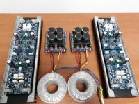
My amplifier for testing.
Looking great.
Please keep us informed on the progress.
Succes,
Hans
Looking great.
Please keep us informed on the progress.
Succes,
Hans
It work !
Hi
XLR input to balanced amps: Bryston uses a pair of differential opamp blocks with their inputs cross-wired to generate balanced drive signals to the two power amps. I believe this is the best solution for the OP, since he was nominally starting with existing stereo PAs. This overall scheme requires no modification of the PAs, nor cross-connecting them, or any other trick that might be used in an integrated balanced design.
In the OP's original drawing, his mistake was to show a signal into pin-1 of the XLR. Although this could represent a ground difference, it does make it look nonintuitive to tie pin-1 to chassis as it should be. The independent PAs cannot really do anything about common-mode signals, where the cross-diff arrangement above can.
Last edited:
SARA-2016 amplifier in full balanced mode. In the first pic QA401 without "atten", in the second one with "atten". The amplifier is almost perfectly transparent. The FFT plot has QA401 pattern and distortion level.
Attachments

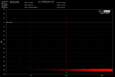
SARA-2016 amplifier in full balanced mode. In the first pic QA401 without "atten", in the second one with "atten". The amplifier is almost perfectly transparent. The FFT plot has QA401 pattern and distortion level.
Good to see that you keep going on and on.
Since your Spkr output is floating, how did you connect the probe of your scope, because signal gnd is no longer a reliable reference.
Or do you have a floating scope on batteries connected directly to the Spkr ?
In that case it would also be nice to record the CMRR by connecting the same input signal between signal gnd and both inputs connected together.
Hans
The measurements are made with QA401 which has differential I/O QA401 Audio Analyzer
– QuantAsylum
The measurements are made with QA401 which has differential I/O QA401 Audio Analyzer
– QuantAsylum
Seems like a wonderful piece of measuring equipment.
Wasn’t familiar with it.
Hans
It is very popular here on diyaudio.it is not perfect but for that money is the best.
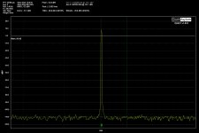
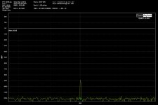
Would it be a lot of work for you to measure the CMRR with the same input level (25mV ?) as in your first THD measurement ?
Hans
Would it be a lot of work for you to measure the CMRR with the same input level (25mV ?) as in your first THD measurement ?
Hans
The input of the power amplifier is at -30.1dBV. The closed loop gain of the amplifier is 32dB. First pic is a "diff" and second one "CM".
Attachments
Last edited:
- Home
- Amplifiers
- Solid State
- Fully balanced amplifier input wiring