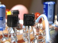
I have tested other transistors than the BF423...also the 2N5401 was used...also the
BC556 was used and now i am testing the BC640 (close cousin related the BD140.... just smaller capsule...and power capacities)
I am always researching....never believe me!...never believe informs....do it by yourself (DIY)... and take your own conclusions...there are billions of Myths over there.
regards,
Carlos
Attachments
Never believe..always put doubts...and go to check
I think that the Solar system is just an atom....planet earth is an electron...our time is very different.... we will spend one year to one turn around the center.... the Sun.
Nebulosis..... constellations are just a part of some living tissue...and black holes are vain drains or celular communication with outside membrane.
Do you believe?..... try to test..if possible!
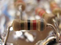
Rail resistor is used because it makes sound better...do you believe?...I do!
hehe
Carlos
I think that the Solar system is just an atom....planet earth is an electron...our time is very different.... we will spend one year to one turn around the center.... the Sun.
Nebulosis..... constellations are just a part of some living tissue...and black holes are vain drains or celular communication with outside membrane.
Do you believe?..... try to test..if possible!
Rail resistor is used because it makes sound better...do you believe?...I do!
hehe
Carlos
Attachments
Universe has no end...of course... things are a box inside a bigger box..that has
another even bigger box outside....this have no end....as we do not accept that things has no end....we call God this end.
But i was wondering...if we are an atomic particule....and we are a powder of a match...and in another dimension someone will ligth that match...what will happens?
Hummm..things may turn hot here...maybe.
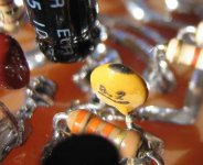
This mess is the supply junction.....maybe the electrons may turn crazy to decide with way to follow.
regards,
Carlos
another even bigger box outside....this have no end....as we do not accept that things has no end....we call God this end.
But i was wondering...if we are an atomic particule....and we are a powder of a match...and in another dimension someone will ligth that match...what will happens?
Hummm..things may turn hot here...maybe.
This mess is the supply junction.....maybe the electrons may turn crazy to decide with way to follow.
regards,
Carlos
Attachments

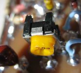
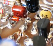
This old zener is pretty, it is a 200 miliwatt unit
Of course you can use 500 miliwatts.... one watt, 5 watts or everyone you find...also you can arrange zener diodes in series..also you can include normal diodes (inverted related the zener ones) to increase 600 milivolts to each diode.
If you have not against fat things...big zener...fat zener..do it...or you have something against fat things....Grrrrrrr!
regards,
Carlos
Attachments
Wondering ... should that 47 uF electrolitic be "bi-polar" rather than polarized ?? ( as indicated on the BOM = C1 ) ... Or does C2 (0.1 uF / 100 nF) take care of this question?

hi FastEddy,
I'll chime in with my limited knowledge. Carlos has built this amp and will no doubt give you the results of "real world" tests, or, it may be a mistake on the schematic. 😉
Normally, you would use a non-polarised cap (or 2 polarised caps back-to-back) for the input cap, but in this case, there is a voltage divider at the input which lowers the voltage through the cap. I read somewhere, most polarised caps will function as non-polarised caps at very low voltages. Sound plausible?
regards
Yes...always prefer the non polarized ones...but those doubts also give us a chance
to produce tests...install a bipolar and them replace and listen.
Also measure the circuit real conditions...measure DC voltage, in stand by mode, fdirectly over the condenser extremes to check if you have polarity there....having measurement you have difference of voltage in one side related the other...DC voltage will be sligtly different.
Related the audio, well, it is AC, and has no polarity...this makes the non polarized ones more adequated.
But you are having small voltages...in the input DC is small and AC is very small too....you will see that the one will work fine.
The 104 capacitor is to create a low resistance to high frequencies to cross the input Dc block.... the use is because of electrolitic condenser inductance...the internal construction is coiled, and this means inductance.....this opposes to high frequencies to cross the electrolitic condenser...so..it will cross the capacitor.
It is not easy...and depends from the sound will cross...but test the amplifier reproducing small bells or metal beeing hitted as a metal triangle...include the capacitor and remove it....keep one side soldered into the circuit and hold te other side with something non magnetic..insert into the circuit and listen...than remove it once more...you may perceive something if your tweaters are fine and your ears working fine too.
Small bells sound have a lot of harmonics, as other sounds also has, but bells reach a very high frequency range...this made you differentiate bells related cymbals and other metal instruments...if you have not the reproduction off all those frequencies you sound will be different from the original....rain falling give you an idea to, but it has more connection to transistor speed than the harmonics...claps also can help.... claps must sound as claps...not as people making noise with their mouthes..astonished because of something.... also claps cannot be confused with rain falling in your roof...that is different from rain falling in the swiming pool...and falling over a metal can.
Also fire can help..... the sound cannot be confused with papper of plastic beeing smashed....the sound when you scratch your hairs/head must be different when you scratch your wooden table.
The capacitor, that 104 one do not works!...you will insert it and remove it and nothing will be perceived...UNLESS the adequated sound having high frequency harmonics will be reproduced..... but normally its presence or absence to not makes a difference...., also the input condenser must be highly inductive...or must have more than 33uf to produce difference...the small ones do not have turns enougth to bother too much.
Never believe!...try by yourself....make the test.
regards,
Carlos
" ... I read somewhere, most polarised caps will function as non-polarised caps at very low voltages. ..."
True enough for hobbiests' work. As a matter of practically and building for the worst case, possibly the use of a higher rated cap would suffice ... maybe 35 VDC max rating in anticipation of possible input spikes >> than line level >> +/- 3 volts.
Just kabitzing here ... I'm sure that DestroyerX has seen these questions come up = input accidently shorted to a power rail, etc.
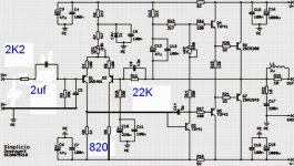
Here is to the worst case...dedicated to you dear Eddy.... a more traditional version
I made tests this morning and did not loose any of the good characteristics the amplifier has.
It is not a good amplifier...it is very BAD!...if you have not a very strong woofer it will fly out of the window holding the coil in flames.
Speaker seem to jump out from the box...and i have one that is sealed....acoustic suspension...nor air enter..no air exaust.
I have installed a small poliester condenser in the input....no...i have not tried another material...you can try if you want.
No losses to the bass...and non polarized capacitor is there.
Also i have removed the attenuator...the input is more traditional to other tastes.
The gain was reduced with the reduction of the 39K resistor that now is 22K...to the more traditional guys happyness.
Also i have changed the feedback colector resistor by a trimpot and i have found that 820 ohms is almost perfect to have the same current in both transistors..... i have made that because the VAS load the input transistor colector...now they have same current.
The off set turns very happy...i could adjust to 300 Microvolts.
The amplifier continues to sound very nice...in this traditional nons shocking form and in the other form too.
I hope more guys turns happy with this option.
I call your attention to the fact that i construct in real life those things...with soldering iron and burning fingers...nothing is only calculated or estimated or simulated...this is real life findings.
regards,
Carlos
Attachments
Re: Here is to the worst case...dedicated to you dear Eddy.... a more traditional ver
Good amplifier small tweaking, Carlos
😎
destroyer X said:I made tests this morning and did not loose any of the good characteristics the amplifier has.
-----------------
The amplifier continues to sound very nice...in this traditional nons shocking form and in the other form too.
I hope more guys turns happy with this option.
Good amplifier small tweaking, Carlos
😎
Thank you dear Lineup....and i will call it Ximple because more international
Maybe this way i will see someone doing it...oh frustration...no one likes my amplifier.
Oh pain
Oh life!
hehe
kidding (more or less)
Carlos
Maybe this way i will see someone doing it...oh frustration...no one likes my amplifier.
Oh pain
Oh life!
hehe
kidding (more or less)
Carlos
We just can't keep up with you Carlos. That does look like a nice simple design, with only 7 active devices. That makes it a real nice option especially for new builders. And if you say it sounds good, I believe you. How about turn on/off noises?
Lineup, maybe you or Mike could sim this one just for fun.
Sheldon
Lineup, maybe you or Mike could sim this one just for fun.
Sheldon
Sheldon said:
Lineup, maybe you or Mike could sim this one just for fun.
Sheldon
I will see if I have those transistors used.
If I have this, I would be able to sim
and get THD, Frequency bahavior and Fourier Analys diagrams.
I thought I had gotten the 2SA1216 + 2SC2922 spice models, today.
But when I tested 2SC2922 at 1 A bias
it shows 0.425 V base-emitter.
So spice model was no good - or does not fit for my MultiSim.
I searched and searched for a better model ... but no luck

=========================
My Audio Power Ouput transistor models I can use, right now is:
MJ15003/04
MJ15024/25
MJL21193/94
MJL3281A/1302A
Until I have added some more good devices into my User Library.
For drivers I have :
MJE15030/31
BD139/140
MJE340/350
BCP-53, BCP-56 ... these are new Philips variants, SMT, of BC639/640 and BD139/140
Models here ( a Philips deicated website for Product Info )
with many components Spice Models:
😎 http://www.nxp.com/models/index.html 😎
lineup
Simulator is a good idea, and lineup can use other transistors...respecting current
and voltage...and beeing audio frequency transistors...no troubles.
Simulator will show some distortion, for sure, as the unique amplifier that sounded good, not stérile, having complex circuit and low distortion was Symassym...the others i have constructed were not good.
Simulators have two problems...the first is that we have always to adjust something in real world.
The second, the main one, is that simulator is unable to tell us how the amplifier sounded...this needs humans listening.
But i will be happy to see some simulation too....but human informs, related audition, are more precious.
I use to listen some Hawaian musics Sheldon..and i remember you surfing in Waimea...Waikiki...i have visited the most beautifull place in this world...that is Honolulu.....maybe there are others even better...but i had not the chance to visit.
Aloha
Carlos
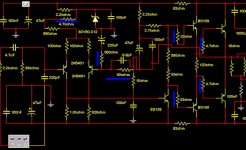
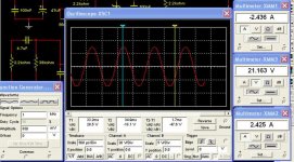
I made the simulation and some adjustments were made to increase the output voltage
The amplifier is linear related power from 20 Hertz to 20 Kilohertz.
Wave shape is fine.
Distortion simulations i do not know how to operate them in Multisim 2001...i will wait some kind friend to do this.
In blue you can see values modified during simulation, to correct the amplifier sensitivity and to increase power.
Tomorrow i will make those modifications in a real world testing.
In the differential, the trimpot was changed to 5K and the 4K7 series resistor was changed to 1K
The feedback resistor is now 10K
Stop resistors changed too.
regards,
Carlos
Attachments
You can see some simulation details here
Attached.
I have tried the removal of the feedback transistor colector resistance...the 820 ohms.
At least in the simulator i could not see any advantage.
I will check this in a real circuit tomorrow
regards,
Carlos
Attached.
I have tried the removal of the feedback transistor colector resistance...the 820 ohms.
At least in the simulator i could not see any advantage.
I will check this in a real circuit tomorrow
regards,
Carlos
Attachments
- Status
- Not open for further replies.
- Home
- Amplifiers
- Solid State
- Full throttle construction of amplifiers