Yes, the intention was not to permanently glue them in, just pressing against the dried flexible glue. Maybe putting some masking tape before I glue it, mount it loosely while the glue dries, and then tighten the screws to 'clamp it'. The masking tape should let go next time I remove the driver.
There will probably still be some resonance, but hopefully higher above the frequency the woofer will be used..
The surface area available (magnet to braces) is limited, so a soft material will not do much I'm afraid, i think it has to be a fairly thin and stiff connection to actually do something. I also have to leave some openings for the vent in the magnet.

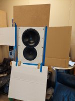
Progress is slow at the moment, but here is a small update with a picture. Have been thinking how to do the radius on the sides of the upper baffle, and I think it will be sheet metal bent over routed radius in the MDF and secured with screws, and the same screws should be used to secure the (removable) upper baffle. It's only placed there in the picture, not fastened in any way.
Taking my time, and trying to solve the problems one by one as they arise..
Did some CLD experiments with 0,5mm alu sheet glued with flexible glue (some of the alu-strips can be seen on bracing in the pic), but I was not too impressed with the result. Gluing alu to both sides of the MDF seemed more effective, but not something I would do on big cabinets like this 🙂. Tried a part of one side too, and compared to the other side of the cabinet. Nothing scientific though, just knocking test. The classic bitumen sheets seem more effective IMHO. When I did that in the past, I could easily hear the change in damping.
I have a feeling that putting some PVA glue on the braces (and in the holes) makes them stiffer. Sounds like resonance goes up in frequency on the braces where I put on some of the excess glue around the openings/holes. Same goes for the braces where I intend to support the magnets.
Thoughts on this from experienced tinkerers?
I forgot to mention that I ordered some sheets of basotect to try out, both for room treatment, and as damping in the cabinets. I remember reading some recommendations about it here somewhere.
Last edited:
Have been routing some bevels and working on the round overs for the upper baffle today. Feels good to see some progress.

Some progress, but still no measurements..
Have put some epoxy-primer on the mdf, some more braces, some sheet metal on the round-overs etc. Trying to figure out what to do to get a more 'integrated look' between the upper and lower cabinets. The 'shelf' in the corners below the round overs disturb me a bit. I could add some chamfers on the lower cabinet I guess, but it also complicates things when I wrap them in vinyl. Another approach could be to just make some gigantic fabric grilles and cover it all up. Similar to this: http://www.troelsgravesen.dk/FUSION/fusion-6.jpg
I temporarily mounted the waveguides and drivers, and sat down and stared at them for an hour or so without getting any 'visions' on what to do, so I figured it was time to go home and sleep on it 🙂
Suggestions? Links with pictures would be appreciated!
You could also go with a less integrated look. You could accentuate the break between cabinets with a groove or paint the upper and lowers slightly different colors, etc. For something like this or the roundover idea, I would normally do multiple CAD models of various treatments to help guide my decisions.
I'll then typically mock it up in paper, cardboard, fome-cor, whatever's appropriate and fast. If you have a decent color printer at your disposal, you can print up whatever paint/vinyl colors you want and tape those on to quickly get a feel for that as well.
I'll then typically mock it up in paper, cardboard, fome-cor, whatever's appropriate and fast. If you have a decent color printer at your disposal, you can print up whatever paint/vinyl colors you want and tape those on to quickly get a feel for that as well.
Another update with some progress, and some bad news..
I have made a jig to place the mid boxes on my gearbox lift, and today I started doing some impedance measurements, but to my surprise I found that the two mids were not the same.. Turns out one is nominal 8ohms, and the other 16ohms (also according to label on driver) 🙁 I sent an email to TLHP where I ordered the drivers, I hope they have good customer support and take care of the shipment error.
I'm planning to use Vcad for the first time in this project, so I have some learning to do.. I'm guessing that getting all the measurements (right) will take some time.
Did some initial FR measurements today. At first it all looked a bit odd, and I could not really understand what was going on. The tweeter did not show the typical WG response with boosted mids and falling towards higher frequencies. I thought it was a tweeter issue first, but when I tried another mic it all looked like what I expected. An expensive B&K mic bites the dust? 🙁
I see two things in the measurements I don't like so far. The tweeter output is a bit low compared to the mid. Ok, not a big issue since the overall response could be EQ:ed with DSP even if it was falling towards the high end. The other issue is the acoustic centers of the drivers is off. The mid is around 1.5cm behind the tweeter, I expected them to be a lot closer. This is not to my liking if I am to stay with passive XO between mid and tweeter. I don't like 'tricking' the phase to align in the passive XO, so running DSP for mid/tweeter XO is more tempting now than before.
I forgot to thank you for the input mattstat, I appreciate the input!
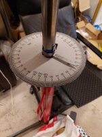
Hopefully I will have some 'quality time' to play around with these more in the weekend. For now focus is more on the technical matters (not design), need to make some angle indicator on the stand so I can make some off axis measurements and start learning to use vcad for the XO sims.
The 16ohm mid is on it's way back, THLP customer support has been good and quick so far!
I see two things in the measurements I don't like so far. The tweeter output is a bit low compared to the mid. Ok, not a big issue since the overall response could be EQ:ed with DSP even if it was falling towards the high end. The other issue is the acoustic centers of the drivers is off. The mid is around 1.5cm behind the tweeter, I expected them to be a lot closer. This is not to my liking if I am to stay with passive XO between mid and tweeter. I don't like 'tricking' the phase to align in the passive XO, so running DSP for mid/tweeter XO is more tempting now than before.
I forgot to thank you for the input mattstat, I appreciate the input!
Hopefully I will have some 'quality time' to play around with these more in the weekend. For now focus is more on the technical matters (not design), need to make some angle indicator on the stand so I can make some off axis measurements and start learning to use vcad for the XO sims.
The 16ohm mid is on it's way back, THLP customer support has been good and quick so far!
I have spent some time playing around with measurements and ''troubleshooting' today.
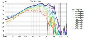
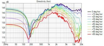
I have a step in the frequency response of the mid around 1,5kHz it dips down almost 3db. I tried playing around with the baffle, a separate cardboard baffle, no baffle etc, but it seems the 'step' is inherent to the driver. It smooths out more than 10 deg off-axis, so not ideal to EQ out either. I'm thinking it's either related to the surround or the plastic 'beauty ring' on the basket. I tried sticking some small pieces of butyl 'goo' to the surround and that seemed to smooth it out some.
The rise from abt 700Hz is baffle step, and the dive around 1.5k is the concern.
I was bit disappointing to find that after looking at Troels measurements and the datasheet, but it seems Troels applied significant smoothing to his measurement, and I expect the datasheet to be even more smoothed.
I played around with active and passive XO in vcad, and with this, and what I mentioned earlier, everything is pointing me in the direction of a fully active system..
Some pics attached
Tweeter is with simple passive HP, mid is without any xo
Attachments

Last edited:
What is your measurement distance?
Is your gating adequate to remove all reflections from near items and walls/floors? If not, backing the microphone up a bit and watching the response trend can sometimes help highlight measurement anomalies that are reflection related. If the dip moves in frequency with microphone distance, it's not a driver issue.
Did you try backing up to 2 meters or so and measuring? Yes, it causes issues with gating/minimum valid frequency, but near measurements can induce there own set of errors.
On the flip side, did you try an actual near-field measurement (within about 1/4 inch of driver cone). It won't be accurate at these frequencies, but some dips and other things inherent to the driver and enclosure interior would still be there.
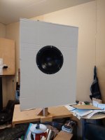
In your third image, is that just a flattener placed in front of your enclosure to eliminate the tweeter geometry or is something else going on?

Is your gating adequate to remove all reflections from near items and walls/floors? If not, backing the microphone up a bit and watching the response trend can sometimes help highlight measurement anomalies that are reflection related. If the dip moves in frequency with microphone distance, it's not a driver issue.
Did you try backing up to 2 meters or so and measuring? Yes, it causes issues with gating/minimum valid frequency, but near measurements can induce there own set of errors.
On the flip side, did you try an actual near-field measurement (within about 1/4 inch of driver cone). It won't be accurate at these frequencies, but some dips and other things inherent to the driver and enclosure interior would still be there.
In your third image, is that just a flattener placed in front of your enclosure to eliminate the tweeter geometry or is something else going on?
The axial dip around 2kHz in the mid is because of the cone being concave - wavelength- dependent phenomenom
https://www.klippel.de/fileadmin/_migrated/content_uploads/KLIPPEL_Sound_Radiation_Poster_01.pdf

https://www.klippel.de/fileadmin/_migrated/content_uploads/KLIPPEL_Sound_Radiation_Poster_01.pdf
A question, the response measurement mid-directivity was that without any make-shift additions?
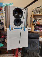
If so, the mid does not look flush mounted. Quite sure that causes the huge dip following the baffle diff bump.
If so, the mid does not look flush mounted. Quite sure that causes the huge dip following the baffle diff bump.
Many replies, thank you, will try to answer them:
Seems like Juhanzi has a suggestion why! Any suggestions on what I could try to actually verify that theory? However, to me it seems like the text would explain the directivity, and dropping off off-axis, but not the dip on-axis and smoother off-axis around 1,5k. The deep off-axis dip around 2.5k looks like that IMHO.
What do you think about the plastic ring on the basket? It's abt a 5mm deep 'cylinder' around the edge of the cone.
1mWhat is your measurement distance?
I think so, did many series of measurements with adjusted gating, they all look similar.Is your gating adequate to remove all reflections from near items and walls/floors? If not, backing the microphone up a bit and watching the response trend can sometimes help highlight measurement anomalies that are reflection related. If the dip moves in frequency with microphone distance, it's not a driver issue.
No.. I never measured that far, except 'in room' responses. I don't have that much space, and the walls in the garage are very reflective.Did you try backing up to 2 meters or so and measuring? Yes, it causes issues with gating/minimum valid frequency, but near measurements can induce there own set of errors.
I did not try that, I have previously had weird results measuring midrange like that (investigating surround resonances etc)On the flip side, did you try an actual near-field measurement (within about 1/4 inch of driver cone). It won't be accurate at these frequencies, but some dips and other things inherent to the driver and enclosure interior would still be there.
It's just the bare driver with a carboard baffle on it, I wanted to eliminate the possibility of issues with my baffle/enclosure. The 'dip' was still there.In your third image, is that just a flattener placed in front of your enclosure to eliminate the tweeter geometry or is something else going on?
Seems like Juhanzi has a suggestion why! Any suggestions on what I could try to actually verify that theory? However, to me it seems like the text would explain the directivity, and dropping off off-axis, but not the dip on-axis and smoother off-axis around 1,5k. The deep off-axis dip around 2.5k looks like that IMHO.
What do you think about the plastic ring on the basket? It's abt a 5mm deep 'cylinder' around the edge of the cone.
It's not 100% flush, the plastic frame on the basket sticks out 1-2mm from the baffle. This is one reason why I tested with the cardboard baffle, that was flush with the driver, different size etc, so should not do much that high in frequency,A question, the response measurement mid-directivity was that without any make-shift additions?
If so, the mid does not look flush mounted. Quite sure that causes the huge dip following the baffle diff bump.
I'd probably start by measuring the depth of the cone to see if the math is in the ballpark.Any suggestions on what I could try to actually verify that theory?
That response looks to be quite consistent with angle, if you look at the normalized graph it will show where there are areas of uneven directivity.The rise from abt 700Hz is baffle step, and the dive around 1.5k is the concern.
It looks quite normal to me. Remember the scales make things look very different. Vituix is quite squished up which makes things look bad, Troels does it the other way and stretches out the frequency scale. If you did the same much of the differences appear to vanish.
For an example look at the Purifi datasheet, the top graph is stretched out and makes the breakups look quite mild, then further down there is a square looking off axis graph where it makes them look much worse, except they are the same thing.
Maybe I'm obsessing about it, but I was expecting a smooth driver, and IMO it's not very smooth.
I have looked at the graphs in ARTA that I normally use for measurements, and it looks bad to me there too, a steep 3dB dive at 1,5k. The off-axis smooths out, so it's probably not a big concern with the room response, but since I'm stuck in my old ways of thinking, on-axis is priority. 🙂
I actually listened to it for a while in mono yesterday evening, with really basic filters in EQ APO (nothing to EQ peaks/dips), and it sounded ok. Tuned filters by ear, and then measured after listening, and it had a pretty smooth falling on-axis response, as is my preference.
Scale... 20¤ off-axis is pretty smooth. With no-baffle this phenomenom is exaggerated! Similar thing happens with deep waveguides and horns tweeters.
ps. This young rallyfinne comes from my hometown! https://www.wrc.com/en/championship/teams-and-drivers/wrc/drivers/kalle-rovanpera/

ps. This young rallyfinne comes from my hometown! https://www.wrc.com/en/championship/teams-and-drivers/wrc/drivers/kalle-rovanpera/
Amazing season by Kalle, a super talent! I'm from Finland too, but living in Sweden since more than 20 years. Not a rally driver though, just got that nickname after rolling a car 😉
Do you have any suggestion of some 'tweak' just to verify this? I guess I can't permanently fix it, but I would be curious to verify the theory. Cut a piece of cardboard to make a 'flat dustcap' and see what it does to the dip?
BTW, the posted graphs are of the drivers in my cabinet/baffle. I made hundreds of measurements in the weekend with the baffle variation in the pics, and also without baffle.
- Home
- Loudspeakers
- Multi-Way
- Full size 3-way project