Since you need high directivity, best to follow the pioneer's way to finding the best XO point in the driver's pistonic BW by calculating each driver's mean using each driver's VC diameter frequency.
'Sound is round', so to speak, i.e. an exponential expansion [1/f] = octave spread, so to find a driver's acoustical half power/XO point [-f3D] we need to know where it's no longer pistonic = the effective diameter of the VC, so a 'close enough' frequency [VCf] for speaker design is its published dia., [Fs], then -f3D = sqrt [VCf * Fs] and if more XO points, then 2-f3D = sqrt[VCf *-f3D], 3-f3D = sqrt[VCf * 2-f3D], etc..
Is there a benefit from this, compared to just measuring the FR and directivity, and trying to match that in XO point?
I'm thinking baffle step sets the XO-point woofer to mid (they should both be pistonic in the 400Hz range), and directivity and driver behavior/limitations set the XO-pint mid to tweeter. 8NMB420 mid seems pretty well behaved according to Troels measurements here: http://www.troelsgravesen.dk/midrange-drivers.htm
Then it's a matter of finding a compromise for that to hand over to the waveguided tweeter. I'm thinking measurements and 'some' listening/tweaking.. I expect it to end up around 2kHz.
Last edited:
Seems like it would save a lot of time/effort and IME (and many others ages ago) know it works well, a good thing since doing DIY measurements ~40-60 yrs ago was a very time consuming and not particularly cheap endeavor and if BSC is required, then assumed it could be handled using the woofer's listed DSP, though 'we' typically did it acoustically in the box design combined with driver selection/quantity since we wanted all the efficiency we could afford.
Only one way to know for sure though is do it your way and compare with the calculations, sim them both and compare.
Only one way to know for sure though is do it your way and compare with the calculations, sim them both and compare.
Sorry, still don't get it.. Are you referring to the upper or lower limits of the driver? Lower I know can be simulated using software (box volume, TSP etc), and higher can be seen in measurements off axis, ringing etc. Radiation is supposed to be pretty predictable (in simulations) as long as the cone is working as a piston. Are you saying that the pistonic range can be calculated from VC diameter and cone diameter? I thought that would differ a lot between cone materials etc.?
I have been wrestling with sketchup on and off for the last couple of days. My skills are improving, but there is still a lot to improve.
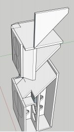
Below are two versions. One 'simpler' with everything in one box, and one that involves a bit more work and parts that is split in two.
I have gone with 22mm MDF, since that is what seems to be readily available around here. I have some braces in there, but thinking I might try some CLD too.
There is more than one sheet of MDF needed for each speaker, even the simpler one. Measurements are H100cm(+2.2cm on the 2-piece version), W50cm, D45cm
I have also gone with the wide and rounded baffle concept. I'm thinking the rounded shapes will be some sheet metal or pipe sections. Behind them are 45deg 'slants' in the baffle, so the radius is just a 'stick on part' for diffraction.
Comments from the experienced builders?
Attachments

IMHO at this scale, there is huge benefit to doing active XO, at least for the low/mid. If you don't, you need large and expensive inductors which are either lossy (air cored) or have non-linearities (iron core). And since you're doing active, do it all active, since who cares about a couple extra channels in the amp box? The mid/high channels need very little power compared to the bass channel so can be very compact.
Using a PC for a crossover is possible but an awful hack. IMHO you will regret doing that for anything except testing purposes and the selection of crossover parameters.
I think you should try an off the shelf DSP, even though it does include an extra DAC/ADC stage. Yes, it is worse in principle than doing it all digitally before the first DAC but the loss of quality is less than what you will face just from the mechanical limitations of pretty much any speaker, and far better than the issues of using a passive crossover at any point! You can start cheaply with something like a Dayton DSP-408 and consider an upgrade to minidsp or whatever later. Latency will not be a problem because you would use the DSP (even if it's only two-way) for both sides of the LF/MF crossover point, so there will be no induced phase error. Or just use the one DSP for all 3 outputs.
If you want to go all analogue, I can sell you a PCB for a 2 channel 4-way 4th order Linkwitz Riley crossover with BSC and APF compensation - or you could design your own pretty easily; the schematics are all pretty textbook and PCB manufacture is incredibly cheap these days. Mine is 100x100mm and uses SMT passives plus 18 dual-opamps. Probably noisier than a DSP with the extra ADC+DAC stages unless you buy super-expensive opamps 🙂 but if definitely won't have quantisation noise at very low signal levels.
I see you have purchased the 15NMB420 already, but they are midbass drivers. I don't think they will give you the low end punch you are probably looking for. You need really strong response and phase linearity in the 40-100Hz band.
22mm MDF is very heavy. It's probably appropriate for the front baffle with your 15" but total overkill elsewhere, especially for the mid/high cab which will not see significant pressures. Everyone else uses 19mm. You get better performance from proper bracing design than thick walls.

Thank you for the comprehensive reply!
When it comes to XO, I have a plan: I will start with 3way EQAPO DSP in PC just for testing as you say ( I have the hardware from previous builds/tests), then the plan is to do passive on mid/tweeter, and use a Minidsp flex for the bass/mid. This will be further down the line though, after verifying that the speaker concept is for me. I can borrow a Minidsp 2x4 from a friend as a temporary solution too, but I found they have a negative effect on the sound.
I like building and modifying stereo amps, so a stack of three will be a bit too much (even if I have plenty of amps lying around). Some are big and heavy class A, and need space around them for cooling. This is what I will most likely be using for mid/tweet. Class AB for bass I think.
If I go 3-way active, placing three stereo amps will be a challenge, and then there is the complication of multi-channel volume control too. Gets expensive fast, been there and backed away. There is now a Minidsp flex 8 that would do the job, but cost is for that is a bit much IMO. I like the specs of the flex units, they measured well on ASR too, so I'm thinking the standard flex would be a fair (but still a bit expensive) compromise.
Thank you for the offer on the analogue XO! I will keep it in mind in case the plan changes for some reason! I don't like dealing with SMT though, my eyes are getting a bit old for that stuff.
I went with the woofers because I found them used at a good price and good condition, and the parameters were similar to the 15PR400 I had in mind from the beginning (many seem to have used those and liked them, Tony Gee, Troels etc). They will start falling off pretty high in the bass, but I figure room gain and some EQ in the DSP will take care of that. They will not be pushed to their maximum anyway, I try to care for what's left of my hearing (51 now). I'm not aware of any sonic disadvantages doing it this way (low Qt sealed box with EQ), as long as woofers are not driven to Xmax? Should be better than BR when it comes to group delay too, I'm thinking? I'm just not a fan of BR..
Interesting thoughts on the MDF thickness.. I have always thought that more thickness and more bracing is always better, and it this case there is a lot of surface area, so I would have used even thicker boards if they were easily available . I hate resonant cabinets..
Actually 22 is a bit thin if I want the woofer to sit flush with the baffle, so I'm thinking that I might surface mount it, and glue on a thinner piece to make it flush Maybe even make some decorative shape on the extra piece. They will get heavy for sure.. more than one MDF board per speaker -some holes +some drivers etc. I think they will need wheels to move around. I still think I will go with the 22mm, since I have drawn them like that, and taken out all the measurements etc. I have to spend many hours in Sketchup if I was to re-do that.
I would never encourage people to do something less than the best they can... but also I think you should focus your efforts on the places that have the most impact on measurable sound quality. IMHO, the biggest causes of bad sound quality these days are: speakers, their boxes, and passive crossovers. Building a bad amplifier takes effort, e.g. by insisting on tubes or broken-headed non-feedback topologies.
As such, I would not bother with Class A amps. By all means, build one for fun, but it sounds like you've already done that 🙂 If you have a stack of 3 good Class A ready to go then I would not dissuade you from using them... but I wouldn't suggest that you build them. The heating bills alone will make you cry!
You can (and I am sure to start a fight here lol) get objective quality just as good even from a chip amp these days at low power levels, without all of the power supply and heatsink and costs. Better performance, in fact, than some of the very simple and popular Class A designs published around here. Conversely if you have passive crossovers, getting those right with a new box design is incredibly difficult, you can't achieve very steep filters, and there are unavoidable quality tradeoffs just because large, high-value high-power filter components are not particularly good, no matter how much they're gold-plated.
So personally, I would* convert from a big Class A with passive crossover to lots of little Class AB with active crossovers in a flash - it will be smaller and probably cheaper and you will reach a very high sound quality level with a lot less effort around crossover tuning.
Tuning an active crossover is pretty easy because it doesn't interact with speaker and box impedances, and that's before you think about the benefits of instantly-modifiable digital designs and the ability to build steep filters that avoid all sorts of speaker physical behaviour issues. So don't think you can design/test with an active crossover, get a good result and then make it passive.
* I do practise what I preach here. My most recent build is a 2.1 system plugged into my computer, all-active. Very lightly-loaded chip-amps for the mid/high and a big old leftover amp for the 12" sub under my desk. Its only real shortcoming is that I made the fronts too small in hindsight, i.e. a failure of box design leading to poor choice of sub/mid crossover frequency.
I think everybody is entitled to their own opinion when it comes to audio, it's like a religion to some, and science to others. For me I'm mainly into the science part, even if I have cases where I think I heard stuff I could not measure.
Anyway, my choices are a mix of science, cost and interest. Amps are a hobby, and I don't see the fun in buying a chip, sorry 🙂 It would be the most cost-effective solution though.
There are some factors that could be beneficial for passive XO, like current distortion in drivers (some discussion going on in the Elsinore-thread), allowing the driver to see a higher impedance. But then again, it could be achieved with some passive components after the amp in a fully active setup too.
I know tuning the passive XO is nowhere near as easy as DSP, but there's a challenge as well.
I think there can be some benefit in testing crossover frequencies and slopes with DSP, to later simulate passive XO to get the same response. Might save some money in components for example.
I want something active at least for the woofer, to be able to tune the bass response to the room, and to get rid of those massive 8and expensive) coils in the passive XO. When it comes to mid/tweeter, I'm not 100% sure yet, but leaning toward passive.
It's still a 'living project', I have already increased the height of the speaker by 10cm, since the volume for the woofer was just over 100L, and I could increase that using the same three sheets of MDF. It is now around 125L instead. I'm also thinking that getting the woofer a bit further from the floor will excite the standing wave (room mode) between floor and ceiling less.
It turns out the 22mm MDF I got was actually 22.5mm, so that complicates things since my drawing is with 22mm thickness. Typical mistake to make, not checking, only assuming.. Now I'm too lazy to redraw everything, so I tried to use my head to change some measurements on the pieces to cut to compensate. Not a very good start to the project.
Hoping to start making some dust this week.
Hoping to start making some dust this week.
It's good practice to cut the pieces intentionally oversize anywhere that you could run a router with a flush cutting bit. That way your cuts don't need to be perfect and the exact thickness of the stock doesn't cause things to be misaligned. Also a mere half millimeter added or subtracted here and there to internal volumes won't do diddly squat to the audible performance unless you're creating slot ports that are mere millimeters wide 🙂It turns out the 22mm MDF I got was actually 22.5mm, so that complicates things since my drawing is with 22mm thickness. Typical mistake to make, not checking, only assuming.. Now I'm too lazy to redraw everything, so I tried to use my head to change some measurements on the pieces to cut to compensate. Not a very good start to the project.
Hoping to start making some dust this week.
Yes, the intention is oversizing baffle pieces etc to run the router to make them flush, but bracing parts growing creates nasty gaps so I have to compensate for that. I don't worry about volumes shifting 1% or so 🙂
This thought probably won't help you now, but I offer it. When I build a cabinet, I do not cut every panel / brace to an exact dimension. I first cut those parts which are fully constrained, such as window pane bracing, and the inner baffle. By fully constrained I mean a panel which will have no exposed edge. From that point, the interior dimensions are fixed, and everything else is cut-to-fit. This way, the outer panels are cut to match the exact width of the constrained panels plus the exact thickness of the sheet material.
Your project is complicated because it is not orthogonal... many strange angles and bevels. When I do something complicated like that, I typically expect to build 3 cabinets and hope that 2 of them are good enough to keep.
Your project is complicated because it is not orthogonal... many strange angles and bevels. When I do something complicated like that, I typically expect to build 3 cabinets and hope that 2 of them are good enough to keep.
I have a tendency to over-complicate things from time to time.. but I felt this is how I want the boxes to be constructed. I really want the rounded edges for the mid/tweeter baffle. Splitting them in two is possibly a bit over the top, but will make it easier to measure/modify/handle them later. If I know myself, there will be a lot of tuning/modifications before I can finally sit back and enjoy the music.
I have to cut everything at one go, when I go to them cut. I only have basic woodworking tools myself. I have planned to do as you said, where the edges are exposed, I added some extra mm's that I can remove with the router later.
I really hope two will be enough 🙂
I have to cut everything at one go, when I go to them cut. I only have basic woodworking tools myself. I have planned to do as you said, where the edges are exposed, I added some extra mm's that I can remove with the router later.
I really hope two will be enough 🙂
Some (minor) progress to report, cut the MDF this weekend, but not all cuts were possible on the saw, so I have to do them 'free hand' I guess. Overcomplicated design.. I think I should have stayed with a one-piece cabinet.
My router packed up when I started cutting holes, so I got a new one today. I did order a new bearing for the old one too, so possibly I will get that up and running later.
Looking at supporting the magnet on the woofer, I think there is some basket resonance going on there, but still have to verify that. I have done this on some cheap drivers with plastic baskets before, made a brace and stuck the magnet to it with some bitumen 'putty'. Problem was that I was never able to remove the woofer after that, so if I go that route, I have to come up with a solution to be able to remove it later. A plate with a tension bar/screw to the back of the cabinet or something.
Measurements are a couple weeks away still, I think.
Some progress to report from the garage. Both bass boxes are now assembled. I mounted a woofer with magnet out to do some basic 'resonance hunting'. I confirmed my suspicion about the basket resonance on the woofers. The light neo magnets and pretty skinny frame gives a resonance around 250Hz. It can be felt when I put my hand on the magnet while music is playing, and I could feel it was strongest when feeding a 250Hz sine to the speaker. I also ran a impedance measurement comparing 'free resonance' and when I pushed my hand against the magnet. Picture of the impedance below. Clear difference!
The rest of the peaks are most likely from box resonances, since there is no stuffing in the box. They are not visible with the driver in free air, same goes for the basket resonance, since the spring(basket)/mass(magnet) has no 'termination' when not mounted to the box.
I think I will try to damp the basket resonance with some elastic glue on the bracing, so the magnet is pushed against it when the woofer is screwed tight to the baffle. Basically 'squeezing' the magnet against some elastic glue. I know it could be done better, but since a friend convinced me it would not be needed, I did not prepare for a better way before I glued everything together. Maybe a softer 'termination' between basket and box could do something too, I usually use some 'memory foam' gasket there. Some experimentation still needed I think. Not sure about the audibility of the resonance, but since I know it's there..
I have played some full range music through the woofers while trying to find panel vibrations, and the box feels pretty good. Sound coming from the woofer is relatively pleasant to the ear too, which corresponds to the claimed smooth frequency response.
The coil on the woofer in the picture below was a temporary test too. Upper baffle placed there just to get a first visual, and maybe some ideas on what it will look like.
Will start on the mid/tweeter boxes later.
Last edited:
"Basically 'squeezing' the magnet against some elastic glue."
What if you want to take the driver off? Perhaps a sheet of polyurethane tightly packed or EPDM rubber?
https://www.etra.fi/en/technical-ru...-e520314/cellular-rubber-sheet-epdm-e52031410
What if you want to take the driver off? Perhaps a sheet of polyurethane tightly packed or EPDM rubber?
https://www.etra.fi/en/technical-ru...-e520314/cellular-rubber-sheet-epdm-e52031410
- Home
- Loudspeakers
- Multi-Way
- Full size 3-way project