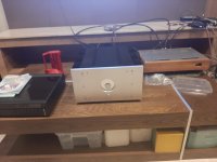
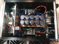
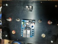
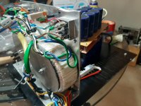
Oh well 3rd world county problem lol
Anyway.. Should be up and running next week. Just tidying up the power supply and cabling
Anyway.. Should be up and running next week. Just tidying up the power supply and cabling
Last edited:
USSPA is different, less big heatsink heat coming from output transistors. Other ntc could have worked if similar enough to original one but not your selected one it seems...🙄
But as I said earlier try bypassing the R11/R12.
Fab
But as I said earlier try bypassing the R11/R12.
Fab
Last edited:
The other channel
The bias and driver current maintain but offset keep drifting towards one direction...
The bias and driver current maintain but offset keep drifting towards one direction...
Your thermistors may not be similar enough between positive and negative sides. Try lifting one one them with 1 or 2 mm from heatsink or further away from driver transistors. Also ensure the N and P channels mosfet heatsink surrounding are st same temperature.
Fab
Fab
Last edited:
For output transistors location on heatsink the optimal position is lower than half the height of the heatsink because heat flow goes toward the top.
Fab
I think you're confusing molecular thermal physics related to convection cooling.
There is a difference between metal heat conduction and airborne heating.
Yes, in the air, heat tends to flow upwards.
But within solids, it radiates from the heat source in all directions.
Hi AnthonyA
You have either wrong or defective parts in your build. This amplifier has been built by 3 different persons with no issue. You have to be more clear on your response (1st or second module, dc offset , ....) by copying the post it applies to. Suspected parts : thermistors and pots for starting. Grounding incomplete ?
Fab
Last edited:
Yes. And it's only one channel
The input is shorted to ground.
All bias, driver current fairly stable. For an hour
But... The DC offset keep going up as time goes by. So far it goes from. Zero to over one volt.
Odd
..
The input is shorted to ground.
All bias, driver current fairly stable. For an hour
But... The DC offset keep going up as time goes by. So far it goes from. Zero to over one volt.
Odd
..
Last edited:
Do you mean one channel is stable but the other one remains with a dc offset issue?
How did you fix the under temperature compensation due to the wrong thermistor part number?
Regarding grounding, ensure the GND tab and the PGND tab on pcb are both connected to PSU ground point. This with OGND that makes the 3 GND tabs connected to PSU ground.
If the dc offset changes it is because the positive and negative part of the circuit do not balance anymore thus the current must be different between the 2.
You should check and record the voltage at the test points as indicated at the manual when you have zero dc offset and then when you have close to 300mv or so. That may lead to one step closer to find the faulty component identification.
Fab
Last edited:
Yes one side stable, the other pcb is drifting
I connect the psu ground to the GND. Which in turn connect to a 10 ohm resistor bypass with cap to chasis and actual ground
What do you mean by both?
I connect the psu ground to the GND. Which in turn connect to a 10 ohm resistor bypass with cap to chasis and actual ground
What do you mean by both?
Good that you have one stable side. 🙂
Let’s concentrate on the other one then.
For the ground, in the end I mean that all 3 grounds terminals on the pcb must connect to the PSU ground on the PSU. The input ground can be shorted with input.
If you perform the measurements again ( not readjustment but only measure) as per the manual before and after DC offset drifting it may help identify faulty part (leaking component or cold solder or else). You will know if the positive or negative is changing or which way.
You can also monitor voltage after the cap multiplier (TP3/GND) and (TP4/GND).
Fab
Last edited:
Lol wrong ground..
PSU supply to OGND and stable
Measure offset via GND and out
Looks stable now lolol
Can you further explain what's 3 ground for and how to use them
I'm very noob.. So my logic is bad
PSU supply to OGND and stable
Measure offset via GND and out
Looks stable now lolol
Can you further explain what's 3 ground for and how to use them
I'm very noob.. So my logic is bad
Last edited:
Excellent! 🙂🙂
The 3 terminals are as follows:
1) OGND is the output ground (may be used to go to speaker load).
2) PGND is the power ground of the pcb going to PSU ground.
OGND is connected on the pcb to the PGND. Thus Since you connect PGND to PSU you can either connect your speaker GND on the PSU board or on the FSSA pcb OGND.
3) GND only connects to R36 (1 ohm) which connects to input/feedback ground on pcb.
The electrical connection from GND to PGND is done by connecting a wire between GND of the FSSA pcb and the PSU ground.
In short, you need at least PGND and GND individual wires going to PSU ground.
Fab
Last edited:
So you mean
GND separate wire to ground of psu
OGND output of speaker(also measure offset OGND vs output)
PGND wire to ground of psu ( to be shared with symetry
Correct ?
Lol I'd so still wrong.. Add a cable again and measure
Pardon my cowardness. I'm not brave lol
GND separate wire to ground of psu
OGND output of speaker(also measure offset OGND vs output)
PGND wire to ground of psu ( to be shared with symetry
Correct ?
Lol I'd so still wrong.. Add a cable again and measure
Pardon my cowardness. I'm not brave lol
Last edited:
Yes correct. As I said earlier OGND use is optional since you can also connect speaker ground to PSU ground. Any diy builder is brave 😉
Fab
Fab


Up and running smoothly.. Thank you papa godzilla
600ma
Speaker protection
CLC. 180000uf of nichicon
Slow start
Full takman carbon. Mox
Just standard canare rca cable
Normal industrial cabling, Belden. Gotham dll.
Cmc rca. Rhodium speaker post local brand
Sound?
Pretty gud! 😎
Nothing weird. That's a good sign
Last edited:
YouTube
It's just mirand dac to amp - you tube clip.. Only 2nd hours
Seem my pre burn in while waiting for parts paid off lol.
It's not customary for Fab to do any review in the first hours but what the heck.
Seem it tick all the boxes of my wishlist VS my diy goldmund a lower biased class AB.
More bloom.
More timbre.
More musical
Creamy and Airy vocal..
More class A but still good bass and slam
Sneaky good staging
Audio bliss... I'm waiting..
I think I will be a happy camper.
I think I spent less than 800 usd in this build. Cherry on top.
Hi AnthonyA
Nice implementation 🙂
I like your chassis and specially your front plate. Is the Meter working?
With this chassis you can sure go higher in class A with more bias current😉
Thanks for posting your build and sharing your impressions. I am glad that your first impressions are already good. I really appreciate the feedback because I put a lot of efforts in all this 😛
Thanks also for the video and do not hesitate to report more when the breakin is more advanced
Fab
Your selling yourself short as a gorilla. Your my papa godzilla
I think I'll stay with this bias for now it's already warm with air-conditioned which mean it's going to be pretty hot without.. Our ambient temperature is 28 deg c and can shoot up to 35 deg c.. So that's why I'm seem like a chicken shiet scary cat diyer. Heat is a big problem here. I'll stick to this until I can monitor them during hot weather
For other diyer... Fab design is always well thought out.. The topology seem simple but they are optimized! And well supported and I believe him he worked extremely hard. You can see he is always serious to help
The success rate is thus higher than normal. That's why I never hesitate to do Fab stuffs seriously. Also pinnocchio also a good friend here. He did every type of diy.. You name it and Fab comes on top. So... Do yourself a favor and do eeettt
- Home
- Amplifiers
- Solid State
- FSSA amplifier build thread with review