I applaud a thorough visual inspection!
Thanks for PDF manual--- a HUGE improvement.
I rely heavily on powered troubleshooting, so please exercise safe procedures to protect yourself.
That you see low voltage at speaker output is encouraging, but at same time I'm baffled that output trimmer is unresponsive. That's probably worth exploring/understanding. Would you report output voltage, say at L601 or any similar convenient point, and input-pair base voltages at R615 and R627. That's a first pass at expected feedback behavior around the amp. You should also see +0.6V at TP K and -0.6V at TP L and these voltages should appear across VR601 and at the wiper terminal as the pot is adjusted. There should be nominal gain from pot wiper to the amp output of -(R673/R627) = -0.22 V/V, or about +/- 130mV at output as pot is adjusted stop-to-stop. If isn't the behavior seen, something's amiss and needs to be understood.
I've described one channel, but there are analogous points on the other channel to be looked at as well.
Maybe this is a good first experimental exercise...
Steve
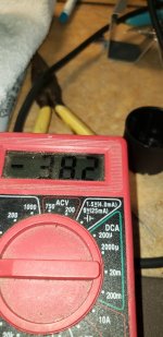
I have 7.6vdc at L601, 7vdc on one side of r615 and r616 and 0vdc on the other legs. I have a cycling 7vdc to 8.4vdc on one leg of R627 and 1vdc on the other leg of R627.I applaud a thorough visual inspection!
Thanks for PDF manual--- a HUGE improvement.
I rely heavily on powered troubleshooting, so please exercise safe procedures to protect yourself.
That you see low voltage at speaker output is encouraging, but at same time I'm baffled that output trimmer is unresponsive. That's probably worth exploring/understanding. Would you report output voltage, say at L601 or any similar convenient point, and input-pair base voltages at R615 and R627. That's a first pass at expected feedback behavior around the amp. You should also see +0.6V at TP K and -0.6V at TP L and these voltages should appear across VR601 and at the wiper terminal as the pot is adjusted. There should be nominal gain from pot wiper to the amp output of -(R673/R627) = -0.22 V/V, or about +/- 130mV at output as pot is adjusted stop-to-stop. If isn't the behavior seen, something's amiss and needs to be understood.
I've described one channel, but there are analogous points on the other channel to be looked at as well.
Maybe this is a good first experimental exercise...
Steve
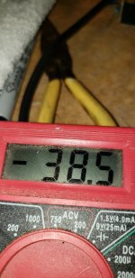
I have a fluctuating 5.4-6vdc on one leg of vr601 and 2.2vdc on the other leg.
I hope I'm covering what you need.
Let me know if this seems correct.

Screw it. I just killed it. I had it unplugged and started to touch up solder joint and arc-ed a transistor. Dim bulb shows direct short.
I'd like to build one of the kits I've seen here and use the chassis and the meters. This amp hasn't been very stable anyway. I just feel awful about ruining it.
Bad luck. Do not lose hope! The silver lining is that there are arguably many “better” diy amps described in this forum that will undoubtedly give you years of enjoyment and pride. Take advantage of decades of amplifier design, measurement, and experimentation since the Proton was released. I think it’s one of the nicest looking chassis out there, so it’s a fine platform from which to start. I think I’ve even seen an example or two in the forum of repurposed D1200 guts.
As a relative layperson who’s built a few amps and read thousands of threads here over the years, I’d recommend using it to build a proven class A/B design (Honeybadger, FH9HVX, or Pass AB100), chip amp (Modulus 86/186/286 or the recent TDA7293 amps) smaller class A amp (ACA or ACA mini), or a robust class D amp (IcePower, Hypex, or TPA3255).
[Caveat: these are just examples off the top of my head. Your requirements or goals may take you in another direction.]
It may seem overwhelming, but DIY is immensely rewarding.
Last edited:

I'm very sorry about your mishap.
Your painful experience has taught me that in similar situations, I should install temporary bleeder resistors to discharge the bulk caps. I was also led to recall a very smart boss/mentor who would occasionally forget to turn off bench supplies while soldering a modification. He modified his soldering iron to insert a current limit resistor in series with a previously hard-grounded iron tip. 🤔 Worked for him!
I can appreciate your inclination to build new hardware in the nice enclosure. Makes sense, but if you want to attempt resurrection, let me know.
Best,
Steve
Thank you for you help.I'm very sorry about your mishap.
Your painful experience has taught me that in similar situations, I should install temporary bleeder resistors to discharge the bulk caps. I was also led to recall a very smart boss/mentor who would occasionally forget to turn off bench supplies while soldering a modification. He modified his soldering iron to insert a current limit resistor in series with a previously hard-grounded iron tip. 🤔 Worked for him!
I can appreciate your inclination to build new hardware in the nice enclosure. Makes sense, but if you want to attempt resurrection, let me know.
Best,
Steve
I couldn't believe what I had done. I looked at the plug and thought I had left it in, but those caps sure store a of energy. I was a bit upset with myself, but only because I made a mistake. Can't blame it on anyone but myself.
I know this is going to make people upset, but I may try a Class D amp inside. I know it's probably sacrilege, but it's economical and I'd like to see what the fuss is about. I would just have to know how I could incorporate the VU meters as they are the draw.
Thanks again.
Scott
No shame in that route! I did something very similar.
Check out these threads for meter ideas.
https://www.diyaudio.com/community/threads/analog-vu-meter-in-power-amplifier.356111/
https://www.diyaudio.com/community/threads/vu-meters-on-a-f5v2.382749/
Check out these threads for meter ideas.
https://www.diyaudio.com/community/threads/analog-vu-meter-in-power-amplifier.356111/
https://www.diyaudio.com/community/threads/vu-meters-on-a-f5v2.382749/
Attachments
Its usually a matter of ruling things out.
A good visual inspection first for dry joints and broken wires etc.
Check power supplies for voltage and ripple. Blown fuses etc.
Check output dc offset. If ok check protection circuit and components.
Check bias current.
Things that tend to go are zener's and electrolytic caps.
Apply a small sine wave to input and follow it through circuit.
If DBT fails I take out output transistors and connect feedback from driver stage to LTP feedback.
This then gives you something tha twill power up without blowing fuses or output transistors.
Wow that's great! Gives me hope that I'll have the big green meters working in a working amp!No shame in that route! I did something very similar.
Check out these threads for meter ideas.
https://www.diyaudio.com/community/threads/analog-vu-meter-in-power-amplifier.356111/
https://www.diyaudio.com/community/threads/vu-meters-on-a-f5v2.382749/
dumb question @nigelwright- what is LTP feedback?
oh and yes I have also caused damage similar to this including the much revered magic smoke- but less so these days after learning from others experiences and skills here
oh and yes I have also caused damage similar to this including the much revered magic smoke- but less so these days after learning from others experiences and skills here
I was just going to ask what would be cut out. Im going to cheat and use 2 mono 1000w Class D amps.I also smoked one of these amps probing trying to set bias. I did rebuild it with AB100 boards off this forum and cut the meter driver portion off the Proton main circuit board at the front and built a small power supply to power the meters. It works perfect.
Can you recall what and where you physically cut and your power supply?
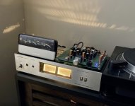
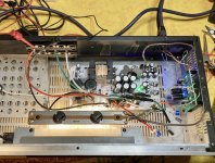
I believe I cut right behind were the screws mount the board on the front cross panel. I've attached pictures of the main board from the top and from the bottom. Also, the end result.


Thanks, I saw that it needs +-14vdc. How did you accomplish that? I suppose 12vdc wouldn't cut it. The amp power supplies have 12v. Then you ran your outputs through the board?The meter board needs +-14VDC.
- Home
- Amplifiers
- Solid State
- Frustration with Proton D1200 Amp