I am at my breaking point with this amp. I don't want to give up on it, but it may get shelved because I am lost. I haven't used it in some years so I decided to bring it out and recap it. I powered it up with a 150w DBT and it came out of protection. I powered right from the wall and it came out of protection. I didn't listen to it because I knew I put it away for a reason and replaced about 10-12 caps. (in hindsight I realize I should have powered it up along the way)
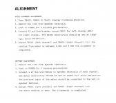
DBT powered on and then bulb went dark, whereas it stayed dim before the caps, and it won't come out of protection. I checked the idle current alignment and have no voltage across R651 or R652. I cleaned VR603 and 604 with deoxit and still nothing. I get intermittent 1.5mv-0mv on the meter and it seems mirrored on each channel.
With the power off I checked VR603 and 604 with a MM and the resistance seems smooth, but I know that these pots should be replaced. I don't want to throw more parts at this thing. I love it, but not that much.
I replaced ZD601 and 602 because the one diode was broken. I also replaced D601 and D602 along with a few resistors around C613 and C614 because some glue corroded the leads.
I am getting frustrated and chasing my tail. What is the first step in troubleshooting? I have walked away from this multiple times in the last few days and I am looking for help with a checklist of forward progress.
Scott
Attachments
Hi Scott,
Frustration is not a good place to troubleshoot from--- I speak from bitter experience. Take a break when needed, as there's reduced tendency to break and/or smash.")
Is this amp a class G or H design? The distinction doesn't matter--- just confirming my guess. Is there a written description that might lead me through the wilderness?
Thanks,
Steve
Frustration is not a good place to troubleshoot from--- I speak from bitter experience. Take a break when needed, as there's reduced tendency to break and/or smash.
Is this amp a class G or H design? The distinction doesn't matter--- just confirming my guess. Is there a written description that might lead me through the wilderness?
Thanks,
Steve
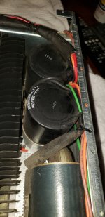
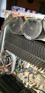
I have two of these amps and blew one up beyond repair accidentally shorting a lead while adjusting bias. These are class AB amps capable of putting 1200 watts into 2 ohms for about 400 mS. They have a normal mode driving the outputs at +-54volts and an instantaneous mode that puts +-109volts on the outputs. Both of my amps had trouble with the large caps for the 109volt rail. There are 4 of these 15000mF in the amp on the outside of the amp next to the transformers. These are prone to swell and arc with time. Unfortunately, I have not found a replacement cap that fits.
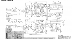
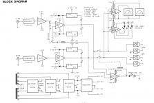
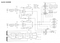
I haven't looked in there yet, Now I am afraid to, I know they are Unobtanium. Here's better schematics and a block diagramI have two of these amps and blew one up beyond repair accidentally shorting a lead while adjusting bias. These are class AB amps capable of putting 1200 watts into 2 ohms for about 400 mS. They have a normal mode driving the outputs at +-54volts and an instantaneous mode that puts +-109volts on the outputs. Both of my amps had trouble with the large caps for the 109volt rail. There are 4 of these 15000mF in the amp on the outside of the amp next to the transformers. These are prone to swell and arc with time. Unfortunately, I have not found a replacement cap that fits.
Attachments
http://www.hifi-classic.net/review/proton-d1200-165.htmlHi Scott,
Frustration is not a good place to troubleshoot from--- I speak from bitter experience. Take a break when needed, as there's reduced tendency to break and/or smash.
Is this amp a class G or H design? The distinction doesn't matter--- just confirming my guess. Is there a written description that might lead me through the wilderness?
Thanks,
Steve
That's what was hot in the late 80's. I bought this new from Crutchfield.
A disclaimer: I'm not familiar with this amp, so I'm working from only the schematic.
I'll make some suggestions and don't hesitate to point out any problems these ideas present.
When powered without any signal present and no load, it there active smoke being generated? If not, then at least active troubleshooting can proceed without provoking more damage.
I suggest that testing be done with 0V input and open circuit loading. What output voltage is observed at the speaker output terminals? Of course it should be near 0V, but perhaps it isn't. How do do any fault indicators correlate with output?
Easy to say, but try to repair any defects that lead to output(s) not 0VDC, again with no signal applied. If this can be achieved, any remaining fault indications may be defective fault sensing, or related to problems in the extended high voltage supplies. As you make progress, beigin to drive with sine wave input. I suggest testing with very light loading to allow large voltage swings without incurring the large output currents that would be required with nominal load resistors. This may ease testing with minimized risk.
Again, good luck, and please advise what you encounter.
If it is still in protection, it won't have anything on the outputs because the relay has not closed. Did you actually move the setting on VR603/604? If you did, the bias is more than likely way off. I would start with getting that set. This is were I blew one amp up. Connect your leads powered down and make sure they are insulated, then power up and adjust the bias/idle current.
I had no smoke. no flashes or arcs. The protection relay doesn't kick in, but I swear I measured 63mv at the outputs. I will double check that when I get home. but there shouldn't be anything present at the outputs if protection is in engaged and the relay hasn't kicked in, correct.A disclaimer: I'm not familiar with this amp, so I'm working from only the schematic.
I'll make some suggestions and don't hesitate to point out any problems these ideas present.
When powered without any signal present and no load, it there active smoke being generated? If not, then at least active troubleshooting can proceed without provoking more damage.
I suggest that testing be done with 0V input and open circuit loading. What output voltage is observed at the speaker output terminals? Of course it should be near 0V, but perhaps it isn't. How do do any fault indicators correlate with output?
Easy to say, but try to repair any defects that lead to output(s) not 0VDC, again with no signal applied. If this can be achieved, any remaining fault indications may be defective fault sensing, or related to problems in the extended high voltage supplies. As you make progress, beigin to drive with sine wave input. I suggest testing with very light loading to allow large voltage swings without incurring the large output currents that would be required with nominal load resistors. This may ease testing with minimized risk.
Again, good luck, and please advise what you encounter.
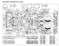
As of now I am stuck with where to measure voltages, I physically need to locate points on the PCB to take measurements. I'm far from an engineer, so be gentle, I, however, can learn quickly
I have tried and there's no voltage. Meter reads 0.00 and then with any kind of movement, tiny movement, I swear I see 1.5mv pop up. I'm at work, but I have tried at least 10 times. Clipping my hooks to the protruded leads of the resistor from the bottom of the PCB and from the top, clipping to an adjacent resistor lead and the emitter that is tied to the resistor R652. I get the same quirky readings. 0.00 with a blip of 1.5mv. The pots are original and I cleaned them and measured them. They seemed smooth for being old crappy pots.If it is still in protection, it won't have anything on the outputs because the relay has not closed. Did you actually move the setting on VR603/604? If you did, the bias is more than likely way off. I would start with getting that set. This is were I blew one amp up. Connect your leads powered down and make sure they are insulated, then power up and adjust the bias/idle current.
Erratic reading are certainly a possibility. Transistors can degrade over time, become leaky. There's a phenomenon known as "pop corn" noise in semiconductors that can present as sudden jumps in voltage. Improved processes have helped this issue but it still occurs. Caps can also go leaky and present as noise, especially mica caps.
As a place to start, look at amp output (ahead of relay if necessary), and the base voltages of the input differential pair. These points should be a very few mV and nearly equal. You can report measurements if you're uncertain about interpretation. How does output respond to trimmer pot? Be sure to compare with similar points in other channel for insights.
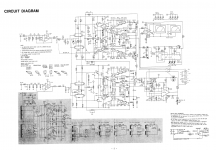
BTW, do you have a link to a better schematic? My copy is kinda marginal.
As a place to start, look at amp output (ahead of relay if necessary), and the base voltages of the input differential pair. These points should be a very few mV and nearly equal. You can report measurements if you're uncertain about interpretation. How does output respond to trimmer pot? Be sure to compare with similar points in other channel for insights.
BTW, do you have a link to a better schematic? My copy is kinda marginal.
The trimmer does nothing. It's as clean as it's going to get and I see nothing moving on the MM. I checked it's resistance with my MM and is seemed to read smoothly.Erratic reading are certainly a possibility. Transistors can degrade over time, become leaky. There's a phenomenon known as "pop corn" noise in semiconductors that can present as sudden jumps in voltage. Improved processes have helped this issue but it still occurs. Caps can also go leaky and present as noise, especially mica caps.
As a place to start, look at amp output (ahead of relay if necessary), and the base voltages of the input differential pair. These points should be a very few mV and nearly equal. You can report measurements if you're uncertain about interpretation. How does output respond to trimmer pot? Be sure to compare with similar points in other channel for insights.
BTW, do you have a link to a better schematic? My copy is kinda marginal.
This PDF my be better, it's the original SM. I wasn't sure if I could attach it. If you give me points to measure on the PCB I will happily do whatever you need. I should write down what I have tried and measured, because I believe I checked on the input side of the relay. No matter I will check again.
Attachments
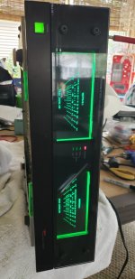
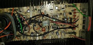
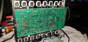
personally and having repaired several Proton electronics, I will start by returning the amp, removing the plate under the device and checking the welds and I mean, all the welds.
it's a very good amp, a little messy but with a lot of energy, however the construction is mediocre.
it's a very good amp, a little messy but with a lot of energy, however the construction is mediocre.
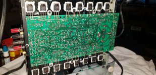
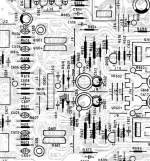
Yes, I believe you. There are some sketchy joints from the factory, a servicing and most likely me. Where you see one? Just ballpark it on the picture. I'm curious.all solder joints
it took me less than a minute to find a suspicious joint from your photo
- Home
- Amplifiers
- Solid State
- Frustration with Proton D1200 Amp