I have one more comparison that I think shows that it is the corners that are ringing into the decay.
It is a comparison of plates used in the baffle with 1khz tuned holes and holes for a 3khz-1khz range. Both were in the large 2'X2' baffle. The same everything, I just changed the plates. If you look at 2.5khz, the splash and ringing are zapped by the baffle before the wave hits the corner. (my theory anyway)
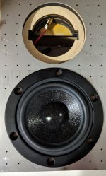
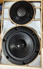
I attached images of what the 1khz and mixed freq. plates look like. Behind the plate are melamine and airspace. Felt sits on the top.
It is a comparison of plates used in the baffle with 1khz tuned holes and holes for a 3khz-1khz range. Both were in the large 2'X2' baffle. The same everything, I just changed the plates. If you look at 2.5khz, the splash and ringing are zapped by the baffle before the wave hits the corner. (my theory anyway)
I attached images of what the 1khz and mixed freq. plates look like. Behind the plate are melamine and airspace. Felt sits on the top.
Attachments
Last edited:
Yeah the delay is equal to distance on the baffle from driver to the edge. No baffle surface or no edge = minimum delay that can be achieved.
Headshake, very high tech baffle, takes a lot of effort! If flat front surface is desired for looks you seem to have a solution. However I have a hunch from the simulations that minimal baffle would be better still 🙂 Not sure which one is easier to manufacture though (at the garage).
Headshake, very high tech baffle, takes a lot of effort! If flat front surface is desired for looks you seem to have a solution. However I have a hunch from the simulations that minimal baffle would be better still 🙂 Not sure which one is easier to manufacture though (at the garage).
Last edited:
Thanks.
I am just using an online laser cutting service. Most of my effort is using an SVG editor.
The perforated sheet design is from a paper by Theodore J. Schultz, Ph.D. from 1986. (Thanks, Dr. Schultz....RIP)
http://www.iperf.org/files/1313/9265/8912/The_Acoustical_Uses_for_Perforated_Metals_Handbook.pdf
https://www.aes.org/aeshc/jaes.obit/JAES_V37_10_PG892.pdf
"However I have a hunch from the simulations that minimal baffle would be better still "
I do wonder if the off-axis is as consistent as a 30mm+ edge radius vs a minimal baffle. I look forward to your sims.
It's interesting what you've managed to achieve with the ripple tank sim, beyond my technical ability.
^^ more simulation attempts perhaps within a week. I can do this only late at night after work and the chores are done 🙂 There is many interesting things to compare, for example the back and sides of the enclosure are creating some splash as well. Here 3" driver, 3kHz signal, 10cm wide baffle and 40cm deep enclosure to demonstrate how much edges on the back diffract.
Attachments

Last edited:
I have one more comparison that I think shows that it is the corners that are ringing into the decay.
It is a comparison of plates used in the baffle with 1khz tuned holes and holes for a 3khz-1khz range. Both were in the large 2'X2' baffle. The same everything, I just changed the plates. If you look at 2.5khz, the splash and ringing are zapped by the baffle before the wave hits the corner. (my theory anyway)
I attached images of what the 1khz and mixed freq. plates look like. Behind the plate are melamine and airspace. Felt sits on the top.
This is some great effort guys, thank you and keep going! I will try to implement this with my stainless steel dipol baffle!
how large are the holes in those baffles and how thick is the absorbing layer behind it? The nomogram in the paper leads me to pretty thick absorber layers which is not really usable on a baffle!
"how large are the holes in those baffles and how thick is the absorbing layer behind it?"
The holes are as small as the laser cutting service can do- 1.2mm. If you are following the paper:
use the smallest hole size you can
use 1/2 airspace and 1/2 foam (foam is against the plate)
use small chambers to increase the angles that the plate works
target frequencies with the plate when the airspace is small
There is only 10mm behind the plate. The foam is 5mm and the airgap is 5mm. I am seeing -6db in the decay on-axis for the target frequency. The inner walls are 3mm and the outer wall is 4mm.
Use this to calculate the spacing for the holes:
Perforated Sheet Open Area Calculation
" The nomogram in the paper leads me to pretty thick absorber layers which is not really usable on a baffle!"
It sounds like you are reading the broadband part of the paper. This is why my plate is not broadband and is targeted-the airgap is smaller than the freqs..
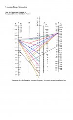
Once you know your plate thickness and hole size you can calculate the throat for the nomogram. What is cool is you can use the nomogram right to left to target things. I attached the nomogram I used to determine the open area for one of my test sheets. You can see how even if the spacing is small, you can target whatever you like. The only downside is the effect is very narrow.
Also, adding felt on top of the plate can help with higher frequencies:
SAGE Journals: Your gateway to world-class journal research
The holes are as small as the laser cutting service can do- 1.2mm. If you are following the paper:
use the smallest hole size you can
use 1/2 airspace and 1/2 foam (foam is against the plate)
use small chambers to increase the angles that the plate works
target frequencies with the plate when the airspace is small
There is only 10mm behind the plate. The foam is 5mm and the airgap is 5mm. I am seeing -6db in the decay on-axis for the target frequency. The inner walls are 3mm and the outer wall is 4mm.
Use this to calculate the spacing for the holes:
Perforated Sheet Open Area Calculation
" The nomogram in the paper leads me to pretty thick absorber layers which is not really usable on a baffle!"
It sounds like you are reading the broadband part of the paper. This is why my plate is not broadband and is targeted-the airgap is smaller than the freqs..
Once you know your plate thickness and hole size you can calculate the throat for the nomogram. What is cool is you can use the nomogram right to left to target things. I attached the nomogram I used to determine the open area for one of my test sheets. You can see how even if the spacing is small, you can target whatever you like. The only downside is the effect is very narrow.
Also, adding felt on top of the plate can help with higher frequencies:
SAGE Journals: Your gateway to world-class journal research
Attachments

Do you have a theory (or does the paper propose a theory) on the physical mechanism causing the ringing? Generally, a decaying resonance implies energy storage and energy dissipation. For a physical system (i.e. acoustic vs electrical), resonance usually requires mass and compliance.
It is not obvious to me that diffraction at an edge can physically cause a decaying resonance. Clearly you are measuring a decaying resonance, but I wonder what is causing it?
Great progress by they way. I look forward to hearing them !
j.
It is not obvious to me that diffraction at an edge can physically cause a decaying resonance. Clearly you are measuring a decaying resonance, but I wonder what is causing it?
Great progress by they way. I look forward to hearing them !
j.
Maybe it is some resonance between the baffle edges, back and forth oncey or twicey?🙂 Waterfall plots on post #81 seem to show the decay around 2-3ms which is about 2-3ft.
These decays should be gone if you take the 1ft baffle out? I mean if it is sound diffracting from baffle edges the ~5" x 8"(?) enclosure baffle would have the decay within 1ms. If the sound diffracts around the cabinet and shows in the waterfall plot it should still show less decay with the resonator baffle than with plain straight baffle. Unless it is the drivers / box resonating or some room reflection. Use very fast transient as test signal to get the waterfall to show less than 1ms? dirac impulse or what it is?
These decays should be gone if you take the 1ft baffle out? I mean if it is sound diffracting from baffle edges the ~5" x 8"(?) enclosure baffle would have the decay within 1ms. If the sound diffracts around the cabinet and shows in the waterfall plot it should still show less decay with the resonator baffle than with plain straight baffle. Unless it is the drivers / box resonating or some room reflection. Use very fast transient as test signal to get the waterfall to show less than 1ms? dirac impulse or what it is?
Last edited:
Looked wrong, #81 plot "main fall" is just shy 3.6ms mark and the reduced decay shows up mostly between the 3.6 - 7.1ms lines. If this isn't some kind of calibration or delay error or something it is room reflections. I must admit I have no idea what the settings visible in the water fall plots mean 😀 just want to understand what is happening so kind of asking whats the fuzz.
Last edited:
hifijim,
I only have spitballs. My hope is the plate will clean up the problems. It is not about the baffles, but there is a neat line from the perforated metal paper that I put below. It has me thinking of springiness and the midrange that is super close to the tweeter. If you look at my baffle wave image, some of the issue freqs. cross the mid.
I do look forward to a listening session and your help measuring. I never thought I would get stuck on the last layer of the baffle for so long.
....
I measured the baffle with just the steel plate and no baffle edge. For comparison, I put a 1.2mm thick bamboo version of my baffle on the top.
The measurements were taken in the top right corner. The metal plate has the layout of the image "mpp_multi_labels". The mic is right over 12 holes that are supposed to target 3000hz. You can see the shape of what the plate is doing and that I am not hitting 3000hz, more like 2700hz. If you look at 1300hz, you can see the decay increase with the metal plate.
The measurements around the baffle show a few odd things. The bottom corners look like sawtooth opposites of each other. The multi-plate has 12 holes in the top right corner to target 3000hz- this also cleans up the bottom right corner. It does not seem to help the opposite corner.
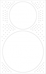
The pic "bafflewave" shows my "bad list" of freqs.: Purple: the freq. measured in the corner of the baffle. It shows the 1/2 WL and full WL. Black: 1/2 WL for the on-axis decay issue freqs.. Green: Full WL for the on-axis decay freqs. Some are shifted because they land on the 1/2 WL of other freqs. It seems odd how the on-axis ones are spaced. Also, many cross the corners or the mid.
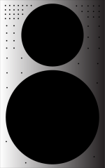
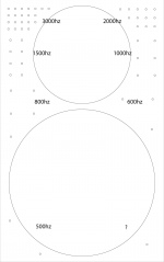
I'm thinking my next plate should have a very narrow coverage since my aim is +/- 200hz right now. Plus the benefit is very narrow according to the measurements. The last image is the current mockup. It only does 2000hz-4000hz in 4 jumps. My fingers are crossed for this to be the "anti-baffle" baffle to get around what I am seeing in the decay.
here is a neat quote about how the absorbers work:
I only have spitballs. My hope is the plate will clean up the problems. It is not about the baffles, but there is a neat line from the perforated metal paper that I put below. It has me thinking of springiness and the midrange that is super close to the tweeter. If you look at my baffle wave image, some of the issue freqs. cross the mid.
I do look forward to a listening session and your help measuring. I never thought I would get stuck on the last layer of the baffle for so long.
....
I measured the baffle with just the steel plate and no baffle edge. For comparison, I put a 1.2mm thick bamboo version of my baffle on the top.
The measurements were taken in the top right corner. The metal plate has the layout of the image "mpp_multi_labels". The mic is right over 12 holes that are supposed to target 3000hz. You can see the shape of what the plate is doing and that I am not hitting 3000hz, more like 2700hz. If you look at 1300hz, you can see the decay increase with the metal plate.
The measurements around the baffle show a few odd things. The bottom corners look like sawtooth opposites of each other. The multi-plate has 12 holes in the top right corner to target 3000hz- this also cleans up the bottom right corner. It does not seem to help the opposite corner.
The pic "bafflewave" shows my "bad list" of freqs.: Purple: the freq. measured in the corner of the baffle. It shows the 1/2 WL and full WL. Black: 1/2 WL for the on-axis decay issue freqs.. Green: Full WL for the on-axis decay freqs. Some are shifted because they land on the 1/2 WL of other freqs. It seems odd how the on-axis ones are spaced. Also, many cross the corners or the mid.
I'm thinking my next plate should have a very narrow coverage since my aim is +/- 200hz right now. Plus the benefit is very narrow according to the measurements. The last image is the current mockup. It only does 2000hz-4000hz in 4 jumps. My fingers are crossed for this to be the "anti-baffle" baffle to get around what I am seeing in the decay.
here is a neat quote about how the absorbers work:
ll resonant devices have a preferred frequency of operation. For example, a ball suspended on a rubber band oscillates at only one frequency, when disturbed: that frequency is determined only by the mass of the ball and the springiness of the rubber band. In a resonant sound absorber, the oscillation involves the motion of air particles, in and out of the holes in the metal sheet, in response to an incident sound wave. The preferred frequency of this oscillation is determined by the mass of the air in the perforations and the springiness of the trapped air layer. At that resonance frequency, the air moves violently in and out of the holes, which pumps the air particles back and forth vigorously within the adjacent sound absorptive layer. There, the acoustic energy (carried by the back-and-forth motion of the air particles) is converted by friction into heat and is thereby removed from the acoustical scene. The practical advantage of the tuned resonant sound absorber is this: we have seen (page 11) that it requires a six-inch layer of sound absorptive blanket if we wish to attenuate sound effectively at low frequencies. Yet, as we have noted above, the treatment of a power transformer requires maximum absorption around 120 Hz. The one-inch layer of glass fiber (shown in the earlier figure on page 11) is only about 5% efficient at that frequency. But the use of perforated metal to make a resonant sound absorber especially tuned to 120 Hz can achieve efficient sound absorption at that frequency without requiring so much space and with only a thin layer of absorptive material.
Attachments

Looked wrong, #81 plot "main fall" is just shy 3.6ms mark and the reduced decay shows up mostly between the 3.6 - 7.1ms lines. If this isn't some kind of calibration or delay error or something it is room reflections. I must admit I have no idea what the settings visible in the water fall plots mean 😀 just want to understand what is happening so kind of asking whats the fuzz.
The speaker is on a metal stand that is about that distance away. I will move some things around. I also want to cover the mid to see what happens.
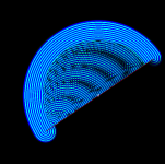
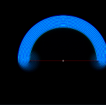
Hi all, I noticed that the ripple tank gives error with angled walls, kind of a bummer... It must be some programming problem or feature why things behave like so. Maybe some rounding error / resolution vs. performance thing.
When wall is straight vertical or horizontal and all is fine, but introduce an angle to the wall and "the errors" appear. The surface of the wall gives million reflections as the wave propagates. This is probably what happens in the reality as well but the jerky resolution on the wall somehow makes this in the simulator very different than with the straight wall (along the simulator x or y axis).
I was experimenting with the corner rounding and bevels and noticed some angles worked better than others and thought it was great info regarding speaker boxes. But, the rotated straight wall test says there is some problem with the simulation instead. I tried to adjust distance of the source to the line but it doesn't help, neither does longer wavelengths.
So, don't use ripple tank simulator for any kind of detailed work or draw hard facts from it 🙂
Attachments

Last edited:
tmuikku,
Thanks again for pointing out earlier that I needed zoom in on the decays. There were some reflections in my measurements. The reflections did not account for all of the issues though.
I still think the sim is showing the decay splash from the baffle dimensions and that I am seeing it in my measurements.
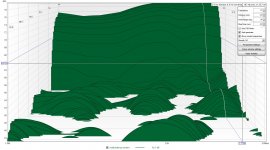
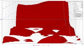
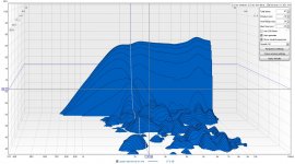
Here are some more measurements that I took this weekend to compare things. Some are with the "mixplate", which is the perforated sheet, and some are a plain wood baffle.
The first two pics are w/ and w/o melamine on my speaker stands on the mixed plate baffle. Mic was in the middle of the baffle.
The next two pics are w/ and w/o a 1.2mm thick bamboo cover over the mid on the mixed plate baffle. Mic was in the upper corner of the baffle.
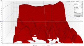
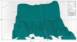
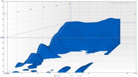
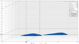
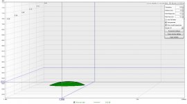
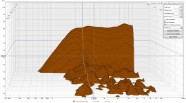
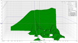
The next two pics are a comparison of the decay between the two baffles in the shortest time scale in REW. In the wood baffle, these two humps form up to make a resonance that is at a frequency that has a WL that is the average distance of the baffle dimensions. It seems like the splash happens when a 1/2WL hits one corner and the full WL hits the other. The mid might be involved too. What is cool is the perf. plate can get rid of them. The mic was 1ft away and at the tweeter's level.
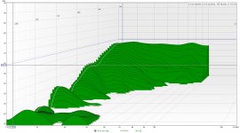
The last two images are a bit further out than the last. Since the decay is wrong from the get-go, every bounce repeats this pattern. It is also the pattern that shows up in the ripple tank sim- a big out-of-place hump in the decay. The mic was 1ft away and at the tweeter's level.
Thanks again for pointing out earlier that I needed zoom in on the decays. There were some reflections in my measurements. The reflections did not account for all of the issues though.
I still think the sim is showing the decay splash from the baffle dimensions and that I am seeing it in my measurements.
Here are some more measurements that I took this weekend to compare things. Some are with the "mixplate", which is the perforated sheet, and some are a plain wood baffle.
The first two pics are w/ and w/o melamine on my speaker stands on the mixed plate baffle. Mic was in the middle of the baffle.
The next two pics are w/ and w/o a 1.2mm thick bamboo cover over the mid on the mixed plate baffle. Mic was in the upper corner of the baffle.
The next two pics are a comparison of the decay between the two baffles in the shortest time scale in REW. In the wood baffle, these two humps form up to make a resonance that is at a frequency that has a WL that is the average distance of the baffle dimensions. It seems like the splash happens when a 1/2WL hits one corner and the full WL hits the other. The mid might be involved too. What is cool is the perf. plate can get rid of them. The mic was 1ft away and at the tweeter's level.
The last two images are a bit further out than the last. Since the decay is wrong from the get-go, every bounce repeats this pattern. It is also the pattern that shows up in the ripple tank sim- a big out-of-place hump in the decay. The mic was 1ft away and at the tweeter's level.
Attachments
-
 wood baffle _badEQ.jpg290.9 KB · Views: 64
 -
 woodbaff_1ft_decay_close2.jpg206.3 KB · Views: 70
 -
 mixPlate_1ft_eqfix_close2.jpg200.7 KB · Views: 69
 -
 mixPlate_close_to_baffle_mid_exposed.jpg336.3 KB · Views: 69
 -
 mixPlate_close_to_baffle_mid_covered.jpg334.6 KB · Views: 71
 -
 mixPlate_CenterBaff_NoMelamine.jpg330.1 KB · Views: 64
 -
 mixPlate_CenterBaff_Melamine.jpg362.6 KB · Views: 71
 -
 mixPlate_1ft_eqfix.jpg266.7 KB · Views: 68
Last edited:
- Home
- Loudspeakers
- Multi-Way
- front baffle width & driver size relation