Just a bit of a recap on the simulation results for the 15ndl88 in a 600mm wide and 820mm high baffle, what we see in the simulation is a gradual gain from low to high frequency stemming from first the baffle and later from the driver dispersion narrowing, the dips we see are the diffraction losses occurring at intervals upward in frequency, is this a correct interpretation?
The driver narrowing isn't going to necessarily increase the frontal output, but rather change the ratio of front to sides. Usually you'd think of it reducing the sides. Also, this means it interacts less with the edges.
I think the term 'losses' is the wrong word to use when it comes to diffraction, as the energy that is displaced is still of interest. In the case you mentioned it can cause variations both up and down, but also in time.
I think the term 'losses' is the wrong word to use when it comes to diffraction, as the energy that is displaced is still of interest. In the case you mentioned it can cause variations both up and down, but also in time.
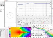
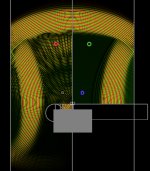
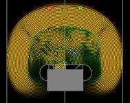
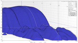
martinsson, here is few diffraction tool examples for your case. The baffle and driver size has only small diffraction ripple. Most of the wild looking things in the polar graph are just due to driver beaming or self interference or what is the right term. This is ideal driver doesn't exactly match reality.
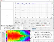
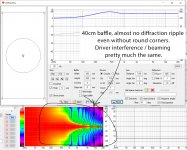
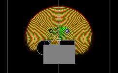
Also two more images, huge 5m baffle showing lot worse diffraction ripple. All the driver beaming related stuff is the same here as well as in a 40cm baffle. 40cm baffle has only little less diffraction ripple than the 60cm baffle. These two attachments have the directivity window graph normalized meaning that 0 axis "ripple" is perfectly EQd flat. This only moves the problem from on-axis to off-axis so not advisable thing to do on a real speaker, but the diffraction is more easily seen on the polar map for evaluating purposes.
Also two more images, huge 5m baffle showing lot worse diffraction ripple. All the driver beaming related stuff is the same here as well as in a 40cm baffle. 40cm baffle has only little less diffraction ripple than the 60cm baffle. These two attachments have the directivity window graph normalized meaning that 0 axis "ripple" is perfectly EQd flat. This only moves the problem from on-axis to off-axis so not advisable thing to do on a real speaker, but the diffraction is more easily seen on the polar map for evaluating purposes.
Attachments
By diffraction losses I mean the destructive interference caused by the difference in distance from driver direct output and baffle edge "splash back" towards the listener or simulation measurement point, but maybe I misunderstand the propagation patterns that emerge in this case.
Thanks, I missed your last post. I was writing my reply at the time, please disregard my previous post.
This is very educational, thank you so much, it is good to know which deviation in a plot or graph stems from what function or mechanism, I need to process this a bit more, eventually I will understand 🙂
This is very educational, thank you so much, it is good to know which deviation in a plot or graph stems from what function or mechanism, I need to process this a bit more, eventually I will understand 🙂
According to the simulations above a 60cm wide baffle will provide a bit more output, about one dB or so, at 200Hz compared to the 40cm wide baffle, the gain signature is similar only adjusted downwards in frequency a bit, which is what I want and I will cross over around 1k.
Yep, but the low end could be boosted with EQ or if it is passive crossover a bit different size crossover component. Small ripple from the diffraction below 1kHz cannot be fixed with EQ so the 40cm wide baffle would be slightly better in this regard. 60cm wide baffle is not too bad, go for it 🙂
True, I'm just thinking that if going with a qtc 0.55 closed design that will start to fall at ~400Hz and reach its f-3dB at ~100Hz (not counting on room gain which is somewhat unpredictable) then a baffle boost would perhaps help a bit, hence I'd rather go for a wider baffle to see if I can at least lessen the alignment drop somewhat knowing I will not be able to null it out all the way down.
By diffraction losses I mean the destructive interference caused by the difference in distance from driver direct output and baffle edge "splash back" towards the listener or simulation measurement point, but maybe I misunderstand the propagation patterns that emerge in this case.
I'm a newb playing with ripple tank, but I see this splash causing issues if the baffle is very small. It seems like all baffles will have a splash unless they are in a wall. In real life, the EDT is where I think I see the issues with the baffle edge messing with the decay- there are certain frequencies that have a decay like they are very close. There are songs where cymbals or "S" sounds don't sound right unless the decay is right. I am still investigating this and wonder what you all think.
The left side of my sim is showing a tuned absorber in the baffle to help with the decay.
side note, a sweet paper on decay and rooms:
Assessing the Acoustic Characteristics of Rooms: A Tutorial with Examples
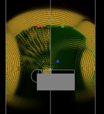
Here is my ripple:
$ 3 1023 127 35 0 1199 0.048828125
202 0 390 553 548 648 0
203 0 421 532 471 532 1 2 8
b 0 470 532 545 582 0
c 0 417 532 471 553 0 10000
e 0 415 563 457 605 0
b 0 397 532 425 571 0
b 0 214 0 467 1018 0
b 0 467 0 719 1018 0
P 1 399 287
P 1 536 287
s 2 463 529 2 2.566663 0 38.274470661478325 147.2095025441474 1 0
s 2 471 529 2 2.566663 0 38.274470661478325 147.2095025441474 1 0
e 0 358 532 431 605 0
P 1 508 486
P 1 427 485
Attachments
Hi Headshake,
I'm not sure which splash part you mean when you say small baffle gives splash? Physical speaker driver starts to beam at some frequency depending on the size of the driver which reduces sound on the baffle at that frequency and above. Thus edge diffraction from a sound from a driver occurs only on longer wavelengths (lower frequencies) than the ones that "beam". On the other extreme, when wavelength is longer than the baffle size, it bends around the corner to the back and gives less and less diffraction the lower the frequency. This leads to simplified conclusion that the splash only happens at a bandwidth between these "extremes". When baffle gets smaller and smaller the extremes become one, baffle size is the same as driver size and minimum splash occurs. Important point is that when the baffle gets smaller there is less overall diffraction splash. Maybe there is something I don't see?
Anyway, I tried ripple tank some more and there are many things that can lead wrong conclusions. For example the canvas edges are not black hole sucking the sound. Instead there is "Absorption area" setting in the options menu and if it is set too small the waves reflect back to the scene. Point sources don't beam and they are very hard to get to the surface of an object etc. For this reason I spent some time to make very rudimentary "generator" that takes more familiar parameters of a loudspeaker box and outputs the Ripple tank settings. Will post it next.
I made helper form to create Ripple tank settings for a simple speaker box with roundovers. It puts the driver on the baffle boundary and helps with the roundovers and some visuals as well depending on the settings. All with familiar settings like baffle width, driver size and corner radius. No more fiddly mouse dragging 🙂
The helper is a single HTML file which displays a form and runs logic on Javascript. The file can be opened in browser after saving it onto your computer. Preview available is visible in the Dropbox but the Javascript doesn't run. See and download here Dropbox - rounded-box.html
Anyway, here are some screenshots what happen with a burst with varying sized box. The smaller the baffle (and enclosure), the better the after echo looks. Large enclosures have longer echo which gets even longer off-axis. Roundovers help but small box seems a lot cleaner than large. It is a 3" driver and 3000kHz frequency, not beaming yet.
Attachments
Last edited:

Another, same set but with 1kHz and 5kHz signals.
At 1kHz the 10cm edge radius is not effective anymore, it looks about the same as without edge radius. Both of these the small box is cleanest looking. edit. The driver should be in beaming zone at 5kHz, but it still wraps around, but can't dive deeper now, time to sleep.
The helper UI aint perfect, but at least it is now possible to do this kind of repeatable comparison sets in few seconds 😀
Attachments
Last edited:
Hi Headshake,
I'm not sure which splash part you mean when you say small baffle gives splash? Physical speaker driver starts to beam at some frequency depending on the size of the driver which reduces sound on the baffle at that frequency and above. Thus edge diffraction from a sound from a driver occurs only on longer wavelengths (lower frequencies) than the ones that "beam". On the other extreme, when wavelength is longer than the baffle size, it bends around the corner to the back and gives less and less diffraction the lower the frequency. This leads to simplified conclusion that the splash only happens at a bandwidth between these "extremes". When baffle gets smaller and smaller the extremes become one, baffle size is the same as driver size and minimum splash occurs. Important point is that when the baffle gets smaller there is less overall diffraction splash. Maybe there is something I don't see?
Anyway, I tried ripple tank some more and there are many things that can lead wrong conclusions. For example the canvas edges are not black hole sucking the sound. Instead there is "Absorption area" setting in the options menu and if it is set too small the waves reflect back to the scene. Point sources don't beam and they are very hard to get to the surface of an object etc. For this reason I spent some time to make very rudimentary "generator" that takes more familiar parameters of a loudspeaker box and outputs the Ripple tank settings. Will post it next.
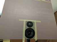
Hi. My focus is on the decay around 2-5khz. I want to target where ears are most sensitive. I use felt to clean up the higher frequencies.
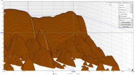
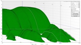
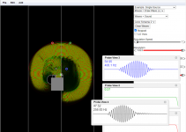
I made the sim to look for things that I am seeing in reality and it confirms it for me. The image "sim decay" shows in black the diffuser vs the plain edge in blue. If you notice in the blue, there is a hump in the decay- this is the splash. In my real measurements, I see this same hump. My second image shows this in the decay at 4khz.
My speaker is all taped up so I can remove the 44mm edge radius (blue graph) and swap it out for a 2'X2' pink foam board (green graph). The next two "between_1ft..." images show what happens when the speaker's baffle gets larger. Notice the change in humps? The ones at 2khz and 3khz are gone for the pink sheet baffle. Since the baffle is larger, the splash is only messing with higher frequencies.
The baffle is only 114mmX182mm w/o the edge radius so it is pretty small. The mid is 3" and the tweeter is 1".
Attachments
Last edited:
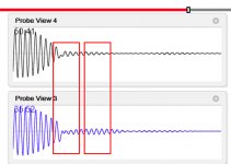
Good rig and big plus for experimenting 🙂 I'll try to understand your data, is the first image from the Ripple tank simulation you posted earlier? The baffle data images: brown shows 4kHz peak but the 4kHz is outside the green and blue decay graphs and timewindow is different? It is a bit hard to compare since the scales are different.
I'm worried since playing with the ripple tank is rather fiddly it gives only indicative results at best. Also at home it is easy to get reflections from surrounding objects about 3ms when mic is 1m away and room height is ~2-3m. I mean 3" travel on baffle yields about 0.2ms of delay between the sound and splash from the edge, or the 1ft baffle roughly 1ms, so I'm not sure if the waterfall plots have the resolution to see the splash? I'm afraid it is some room reflection in the waterfall plots. Not knowing your mic and room setup of course so I might be completely wrong. I'm interested about the issue so thanks for the real data! When I got time I'll device your test in the script so it is easier to change the properties and compare outcome with different widths and roundovers.
Edit: narrow baffle, no splash on the blue probe. Tail of the burst is changed though. I'm not sure what the audible effect is. For example temporal masking kicks in with a small delay so it might be better to have the almost inevitable splash or echo a bit delayed for temporal masking to do the job. Gotta read on that some.
Attachments
Last edited:
" is the first image from the Ripple tank simulation you posted earlier? " Yes.
"brown shows 4kHz peak but the 4kHz is outside the green and blue decay graphs and timewindow is different? It is a bit hard to compare."
The brown and blue are both the same small baffle w/ 44mm edge. The mic was in different spots. For the brown, the mic was at the edge of the baffle to capture as much of the mess as possible. For the green and blue graphs, the mic was in the middle of the baffle. The brown is just there to show the worst hump. The blue and green are meant to be compared.
Thanks for looking at the data/sim. I am a newb and it is easy to get lost in the weeds.
I don't expect the splash to explain all of the mess, just some of it. I have a suspicion that the grill is also doing something bad.
Last edited:
The more newbies we have here the more we make mistakes and learn something 😀 Hopefully some wise people chime in and say what to check and what is good and what is bad experiment. Anyway, it is fun to experiment, just need to be cautious to draw conclusions too early
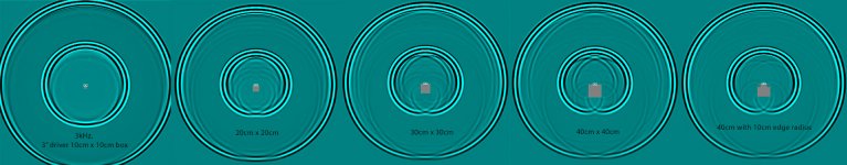
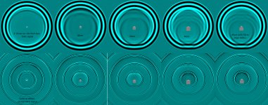
One more example showing the "bandwidth" I've mentioned multiple times now 🙂 Small driver on large baffle has a lot of wiggle (over wide bandwidth), big driver has no wiggle at all. Attachments demonstrate 43cm square baffle, driver in the middle and 0 degrees reference axis to maximize the effect seen on the SPL graph. Attachments are 1", 3", 6.5", 10" and 15" drivers on the same baffle. You'll see the bandwidth that has diffraction "problems" gets narrower until almost disappears on the 15" driver. Last attachment shows ~6.5" driver on ~6.5" baffle and you see there is no wiggle at all.
This means less baffle surface = edges as close to driver as possible, is better. When the baffle edge is right at the driver edge, the frequencies which don't beam are long enough to not cause diffraction at the edges. Makes sense. Slanted edges / roundovers help to get bigger box and still have baffle "edges" close to the drivers. On a direct radiating multiway speaker there is large and small drivers on same baffle so some tricks must be done to minimize baffle area. Google up the Revel Ultima Salon 2 images, pretty much minimal baffle right there 😉 Pulled up the Revel Salon 2 since it is often mentioned here in the forums due to infamous comparison between Salon 2 and JBL M2 some years back. By the way the M2 also has pretty much a minimum baffle area.
First of all what I feel is that if you are measuring the output after the box is built then you are already getting the measured output and if the box needs to be designed then its better to be considered about the baffle shape but a good fluid dynamics sim would be a better choice to look at to see real problems at the microscopic levels.
Part of the problem in my experiments and current discussion is how this all relates to hearing and audibility of these issues. There might or might not be need for micro detail. I don't take any of these tests as hard fact rules but only trying to see all this in relative terms, as a big picture.
For example quickly checked some temporal masking stuff and most of the studies are done in millisecond delays, a lot longer durations than where the splashes typically occur. Could some of this be tested with headphones, two pink noise signals and one has variable delay? I mean if the magnitude of delay that is heard is in microseconds all this is very relevant, change in timbre?
For example quickly checked some temporal masking stuff and most of the studies are done in millisecond delays, a lot longer durations than where the splashes typically occur. Could some of this be tested with headphones, two pink noise signals and one has variable delay? I mean if the magnitude of delay that is heard is in microseconds all this is very relevant, change in timbre?
Last edited:
- Home
- Loudspeakers
- Multi-Way
- front baffle width & driver size relation