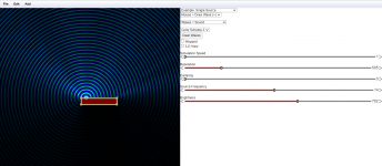
Adjust the brightness and resolution, the diffraction shows as darker and brighter areas as the sources interfere. Some of the different colours are clearer too.
Ok managed to get visuals, point source on a "baffle"
Ripple tank example showing diffraction related ripple
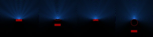
This asymmetric positioning shows nicely some nulls forming from edge diffraction when the simulation speed is slow. Adjusting the box from narrow to wide shows ripple as well with these settings.
edit: Aww the settings aren't included in the link.. Put simulation speed to lowest and set color scheme 3 for good view.
It is a bit hard to adjust the sound source at the box boundary, if the source is away from the boundary there are some additional effects in play 🙂 Anyway, another nice software to visualize stuff.
Ripple tank example showing diffraction related ripple
This asymmetric positioning shows nicely some nulls forming from edge diffraction when the simulation speed is slow. Adjusting the box from narrow to wide shows ripple as well with these settings.
edit: Aww the settings aren't included in the link.. Put simulation speed to lowest and set color scheme 3 for good view.
It is a bit hard to adjust the sound source at the box boundary, if the source is away from the boundary there are some additional effects in play 🙂 Anyway, another nice software to visualize stuff.
Last edited:
A screenshot. Anyone should try to use the animation though, it is fun to see the effect form as function of time!🙂
At first the sound is "pure" at listenig spot but then after the diffraction happens and sums with the direct signal there is attenuation or amplification dependig which angle you are at (and frequency). Other ear might get attenuated signal while the other receives amplified, while at some other frequency it might be vice versa. I guess a slight timbre change happens at least? Not sure how hearing system detects this kind of effects but brain must be having lot of computation going on. Temporal masking relates to this at least. Anyway diffraction seems to be a thing to avoid in a loudspeaker.
At first the sound is "pure" at listenig spot but then after the diffraction happens and sums with the direct signal there is attenuation or amplification dependig which angle you are at (and frequency). Other ear might get attenuated signal while the other receives amplified, while at some other frequency it might be vice versa. I guess a slight timbre change happens at least? Not sure how hearing system detects this kind of effects but brain must be having lot of computation going on. Temporal masking relates to this at least. Anyway diffraction seems to be a thing to avoid in a loudspeaker.
Attachments
Last edited:
it seems that drivers should be placed as close as possible to the top of the baffle and dead center, and that goes for any baffle widths
a tweeter should of course be coaxialy mounted for best system performance, but otherwise a small face plated tweeter should be used and mounted right to the top edge
a tweeter should of course be coaxialy mounted for best system performance, but otherwise a small face plated tweeter should be used and mounted right to the top edge
And why not on a side edge too, i.e. in the corner. Both corners of the loudspeakers looking at each others, i.e. between the listener ? While I assume the 90° edge of the corner should be a big diffraction
any mounting will do, but none work as good as putting the driver dome/cone/diaphragm at the top edge, and dead center
mounting a driver close to a corner and you will loose some low freq baffle step gain, if that is good or bad is up to you
mounting a driver close to a corner and you will loose some low freq baffle step gain, if that is good or bad is up to you
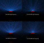
Quick try with Ripple tank to check if curved baffle has advantage over flat baffle and it seems there is no advantage if the baffle edges are sharp. If the edges are rounded there still isn't too much benefit curving the baffle I guess. This is not comprehensive test but given that curved baffle is lot harder to manufacture than flat, a flat with round edges seems the best option for DIY folk, or just use minimal baffle. Wide baffle has advantage to shadow sound going behind the speaker but roundovers need to be generous to attack the diffraction. Narrow baffle (to my eyes) seems as effective as wide with rounded edges but radiates more to the back (higher frequencies, higher bafflestep).
In ripple tank there is no numbers visible and the brightness of lines in the attachment are different so position of the point sound source to the "baffle" is not perfect and this is only one / few frequencies I tested but I think they indicate that rounding the edges reduces the diffraction ripple, other tricks juts change the distribution of the ripple.
Ripple tank link, change color scheme 3. Point source should be at 12.01m x-axis coordinate, baffle left at 10.01m and right 14.01m anyone wants to replicate the stuff in the attachments.
Attachments
Last edited:
^ Hi,
Have you seen Patrick Bateman's test about curved frontbaffle Tmuikku? It seems to be minimal but have an effect still.
Have you seen Patrick Bateman's test about curved frontbaffle Tmuikku? It seems to be minimal but have an effect still.
tmuikku, not sure but I'd check those by widening the baffle across the screen (start with the flat one for ease) to see whether the source might be slightly proud of the wall. Just something I've noticed using that tool with smaller wavelengths.
Hi krivium,
I probably have but don't know which one you mean, do you remember which thread it was?
Yeah the phenomenon has been studied and discussed to death every year but it is fun to experiment so thought to post em here.
I probably have but don't know which one you mean, do you remember which thread it was?
Yeah the phenomenon has been studied and discussed to death every year but it is fun to experiment so thought to post em here.
Using the simulation I've found that a succession of 30 degree chamfers looks as good as a continuous curve.
AllenB, yeah it is very hard to use, no zoom and doing by hand leads error since there is some resolution on my mouse or in the JS canvas. Tried to adjust the source so that it was inside the baffle, then slowly moving (jerking) it out to the surface until bright waves appear 😀 Not very scientific.
If I got time I check if the script can be hacked a bit with browser developer tools.
If I got time I check if the script can be hacked a bit with browser developer tools.
Yes, I'd agree. I like to save from time to time. Full screen is interesting.
David McBean's hornresp uses it (if I'm not mistaken)..
David McBean's hornresp uses it (if I'm not mistaken)..
Yes this one (of many):
https://www.diyaudio.com/forums/mul...fles-lead-narrower-beamwidth.html#post5835922
I must admit i'm still floored by his deduction and it was the first time i understood why baffle step are considered as diffraction.
https://www.diyaudio.com/forums/mul...fles-lead-narrower-beamwidth.html#post5835922
I must admit i'm still floored by his deduction and it was the first time i understood why baffle step are considered as diffraction.
Last edited:
A good thread indeed, but I'm not comfortable with the initial suggested reasons. It seems that some very different things can happen when you open out a baffle, some which seem to conflict, which makes it difficult to draw simple conclusions.
Hi Allen,
You may well be right. I don't know. Patrick's quest is a perpetual works in progress and he point to many directions which is a good source of 'food for thoughts'.
But i must admit i'm convinced by the method/analysis and what he presented in this one.
You may well be right. I don't know. Patrick's quest is a perpetual works in progress and he point to many directions which is a good source of 'food for thoughts'.
But i must admit i'm convinced by the method/analysis and what he presented in this one.
It is very fiddly 🙂 Have you tried adjusting the resolution when moving objects?
I haven't had time to play with it too much yet. Found out the source code is on Github and the export / load settings as test. With the information from source code the text files can be edited by hand to get more precise positioning an sizing of the various objects. Need to look into that later. It would be fun to try some waveguide profiles as well 😀
Last edited:
@ krivium
Badman picked it up in post #6 and I agreed in #8. The phenomena in this particular case appeared to be not about rounded baffles, but about the secondary flare method as described in the '70s and popularised by Tom Danley.
(And there is evidence suggesting it in Patricks post #1)
Badman picked it up in post #6 and I agreed in #8. The phenomena in this particular case appeared to be not about rounded baffles, but about the secondary flare method as described in the '70s and popularised by Tom Danley.
(And there is evidence suggesting it in Patricks post #1)
- Home
- Loudspeakers
- Multi-Way
- front baffle width & driver size relation