hi!
I'm looking for schematics to build me a PLL 50Hz psu for my lp12
I already found some threads around the web but none with schematics, except for this one, but i can't remember where i found it... *stupid*
i'd like to get as close as possible to the specs of a linn lingo ...
so a maximum drift (?) of 0.01 Hz is allowed....
therefore the wienbridge oscilator schematis as used for the garrad 301 is not good enough ( 0.15Hz)
any sugestions?
(i'd like to diy the project so a kit solution like the wnaudio turntable psu is not preffered)
kind regards,
bas
Attachments
additional info
large picture can be found here:
http://www.saturnus.nl/~basdevos/ph.bmp
and of course frequentie is dutch for frequency......
large picture can be found here:
http://www.saturnus.nl/~basdevos/ph.bmp
and of course frequentie is dutch for frequency......
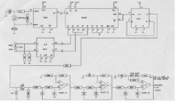
Ha,
That's my design! I gave away my last PCB's on the forum last year. They were leftovers from a commercial venture many years ago. The 40103 chip is difficult (but not impossible) to get now.
The frequency acccuracy will depend largely on the temperature and the grade of capacitor used in the oscillator. If you mount this circuit in it's own box, away from heat generating components, the accuracy can stay very good. There is no need to fit the NTC thermistor in this case.
Remember also that the 301 / 401 motors will vary greatly in speed if the voltage (amplitude) changes, so you must also ensure it remains stable.
Enjoy,
do yourself a favor -- skip the analog filters and grab a sample of the 8th order elliptic filter from Linear Technology. if 50Hz is the frequency you need you can use the self-clocking feature of these filters. (i have burned up some of these chips trying to self-clock too fast.)
it's also helpful to put some thermostatic mechanism in place --
it's also helpful to put some thermostatic mechanism in place --
I understand only half of the story, but it seems you need a very accurate 50Hz sinewave source.
Then why don't you use some numerically controlled oscillator in an FPGA (or CPLD maybe) and an audio-DAC? That way you should be able to generate an ultra-stable 50Hz (just as stable as the crystal oscilator used), and a different frequency is easy also.
You could even take it a step further: drive a MOSFET half-bridge or full-bridge directly from the FPGA/CPLD to synthesize the sinewave directly at the required powerlevel. Add a simple LC filter, and you're done.
dhaen said:Ha,
That's my design! I gave away my last PCB's on the forum last year. They were leftovers from a commercial venture many years ago. The 40103 chip is difficult (but not impossible) to get now.
The frequency acccuracy will depend largely on the temperature and the grade of capacitor used in the oscillator. If you mount this circuit in it's own box, away from heat generating components, the accuracy can stay very good. There is no need to fit the NTC thermistor in this case.
Remember also that the 301 / 401 motors will vary greatly in speed if the voltage (amplitude) changes, so you must also ensure it remains stable.
Enjoy,
Hi,
I'm happy I found the designer ;-)
Do you happen to have any files of the PCB layout?
And are you willing to share these?
I would like to use this design to drive my lp12...
Do you think this design is the way to go...?
To all who answer:
Please take in mind I have only a mediocore knowledge of electronics...
He is already using a cristal-controlled numerical oscillator and a 6-th order low-pass filter. What he wants to improve is the precision of the own cristal oscillator, since there is just no way in which the rest of the circuit could affect the output frequency.
P.S. Ready made expensive black boxes are not always the best solution for our problems.
P.S. Ready made expensive black boxes are not always the best solution for our problems.
Hi,
There are easier ways to go now, such as suggested by Jack, or the other poster's suggestions, but they all rely on you having some experience.
I will reiterate my previous statement that frequency accuracy is not the only important factor, amplitude stability is also important for any synchronous motor. If the amplitude varies, the speed will change, therefore it is not worth going overboard about frequency stability.
If you want, you can feed the output of this circuit into an audio amplifier and "step-up" the voltage using a transformer. It will work.
WRT the analogue filters: You can get them more accurate by choosing better resistor values. The values quoted were used for 50 or 60Hz. Go to the Texas Instruments site and I think you will find a tool for calculating the values.
I'll have a look.Do you happen to have any files of the PCB layout?
There are easier ways to go now, such as suggested by Jack, or the other poster's suggestions, but they all rely on you having some experience.
I will reiterate my previous statement that frequency accuracy is not the only important factor, amplitude stability is also important for any synchronous motor. If the amplitude varies, the speed will change, therefore it is not worth going overboard about frequency stability.
If you want, you can feed the output of this circuit into an audio amplifier and "step-up" the voltage using a transformer. It will work.
WRT the analogue filters: You can get them more accurate by choosing better resistor values. The values quoted were used for 50 or 60Hz. Go to the Texas Instruments site and I think you will find a tool for calculating the values.
Hi DaBit,
Do you know of a datasheet or appnote that illustrates your idea? A google search revealed much fancy stuff, but nothing I could track down to our task.
Rüdiger
DaBit said:
Then why don't you use some numerically controlled oscillator in an FPGA (or CPLD maybe) and an audio-DAC? That way you should be able to generate an ultra-stable 50Hz (just as stable as the crystal oscilator used), and a different frequency is easy also.
Do you know of a datasheet or appnote that illustrates your idea? A google search revealed much fancy stuff, but nothing I could track down to our task.
Rüdiger
he probably refers to something like this...
http://nl.farnell.com/jsp/endecaSearch/partDetail.jsp?SKU=1095815&N=401
the problem with these is is that they are not stable enough...
a crystal oscillator is more stable ...
http://nl.farnell.com/jsp/endecaSearch/partDetail.jsp?SKU=1095815&N=401
the problem with these is is that they are not stable enough...
a crystal oscillator is more stable ...
Hi Bees and others,
in the longer run, I will build something like that for my garrard 401.
What should such a solution provide?
- most stable freq.
- pure sine wave without higher harmonics, 'no' distortion
- stable voltage amplitude
and, in case of my 401:
- power output stage with selectable output voltage swing between 140 and 220V. (to catch the point where the motor produces the least noise and rumble)
Are there any parameters missing?
How would a solution using a AD9835 perform in this respect?
Here is a ready solution (sine wave generation only)
The output stage might be the one from here
But I have no idea what would work best: a complete analog sine wave generator, a filter assembly like that of dhaen (or more up-to-date with filter chip) or digital-dac like in a dds.
Rüdiger
Do you know of a datasheet or appnote that illustrates your idea? A google search revealed much fancy stuff, but nothing I could track down to our task.
No, unfortunately not. But you could make it as 'simple' as an EPROM with address counter and DAC behind it, or as complicated as using an FPGA or DSP driving a H-bridge to synthesize the required waveform.
bees said:he probably refers to something like this...
the problem with these is is that they are not stable enough...
a crystal oscillator is more stable ...
No, I did not. I referred to generating the sinewave digitally, and converting it to the analog realm using a nice audio-DAC.
However, I once used this XR2206 chip in combination with a 4046 PLL chip and a temperature compensated crystal oscillator. That generated a very stable sine also, although you guys might not like the distortion of the XR2206.
That Analog Devices chip looks good too!
- Status
- Not open for further replies.
- Home
- Amplifiers
- Power Supplies
- frequentie locked psu