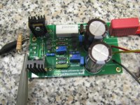
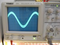
Here you can see some photos, and what I got from the scope.
I can see a sinewave to the Mhz region.
I am thinking to put a small, like 60p, cap between base collector on the 15030.
I can see a sinewave to the Mhz region.
I am thinking to put a small, like 60p, cap between base collector on the 15030.
Attachments
Last edited:
I already checked the board, will check again, but both channels behave the same.
What about the small cap?
What about the small cap?
You can try the small caps.. are you sure the pin of your transistor is cbe when looked from the face?
Yes, I used bc550c and bc560c, they are cbe.
Also be voltages seem OK on all transistors.
Tried small caps no change.
I tried at 100 and 200 mA.
Voltage is around 16V and I have 10000uf and 1ohm before the board.
Also be voltages seem OK on all transistors.
Tried small caps no change.
I tried at 100 and 200 mA.
Voltage is around 16V and I have 10000uf and 1ohm before the board.
in my testing the voltage is +-12V. maybe you should try a lower voltage? did you get zero average output voltage by adjust the pot?
I will try to lower voltage and see.
By adjusting the pot I get near 0 but always a few mV offset. I think this is due to oscillation.
By adjusting the pot I get near 0 but always a few mV offset. I think this is due to oscillation.
I was away for a few days.
I will try later with slower output transistors and see.
I have some mje340 I am thinking to use.
I will try later with slower output transistors and see.
I have some mje340 I am thinking to use.
With mje340 (be careful of the different pinout) and bc546 it works fine. Have not listened it it yet though.
I used mje 15030 in the beginning when I had problems. These seem too fast for this circuit.
Ray, could you advise what exactly transistor did you use?
I used mje 15030 in the beginning when I had problems. These seem too fast for this circuit.
Ray, could you advise what exactly transistor did you use?
This is a great little circuit !!!
I was looking for something like this.
I have now modified this circuit for a higher current and I have it doing about 9.2v peak into 2 ohms, 8.73v peak in to a 1 ohm load, and 6v peak into .5 ohm and will even do a .25 ohm load.
All in class a mode operation in a simulation using Circuitmaker 2000.
With no errors!
I was beginning to think that this was nearly impossible on a +/- 12v supply.
All I did was add 4 more pairs of output devices and juggle a few resistor values.
In this example I have the bias set at 3 amps per device so each one is dissipating 36 watts approximately half of what an MJE3055 can do.
I will try to build this some time in the near future and put it to the test.
But if any one is interested I can post the schematic at any time.
It would be very interesting to know what kind of performance this thing has and could do with the modifications.
Keep on DIYin' !!!
jer 🙂
I guess I was a little over excited in my last post! 🙂
But I was thrilled to see such a low THD figure and in researching the JLH circuit I have found that what I had discovered a lot of DIYer's are already doing this! he,he
I have been looking for a way to build some Class a amplifiers for a reasonable cost and I had found that this may be the ticket vs the Nelson Pass designs.
Both seem to be very popular only I am not willing to track down and pay the price for some jfets that are out of production.
These use BJT's and I already have every thing I need to build these in my box of spare parts, and will still have great performance on the cheap.
Particularly for driving my ESL's.
I had already known of the JLH design but it wasn't until this thread that had got me hooked on the modernized versions of this design that I have found.
So far I have created a design the uses 8 pairs of output devices and is good to 1 or 2 ohms on a +/- 30V supply with little changes to the original circuit.
The design is the same and I could probably build it with new parts for around $10 for just the amps components (using the MJE3055 at $.39 each).
That is alot of amplifier for the price. 🙂
Thank You !!!
jer 🙂
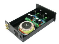
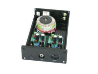
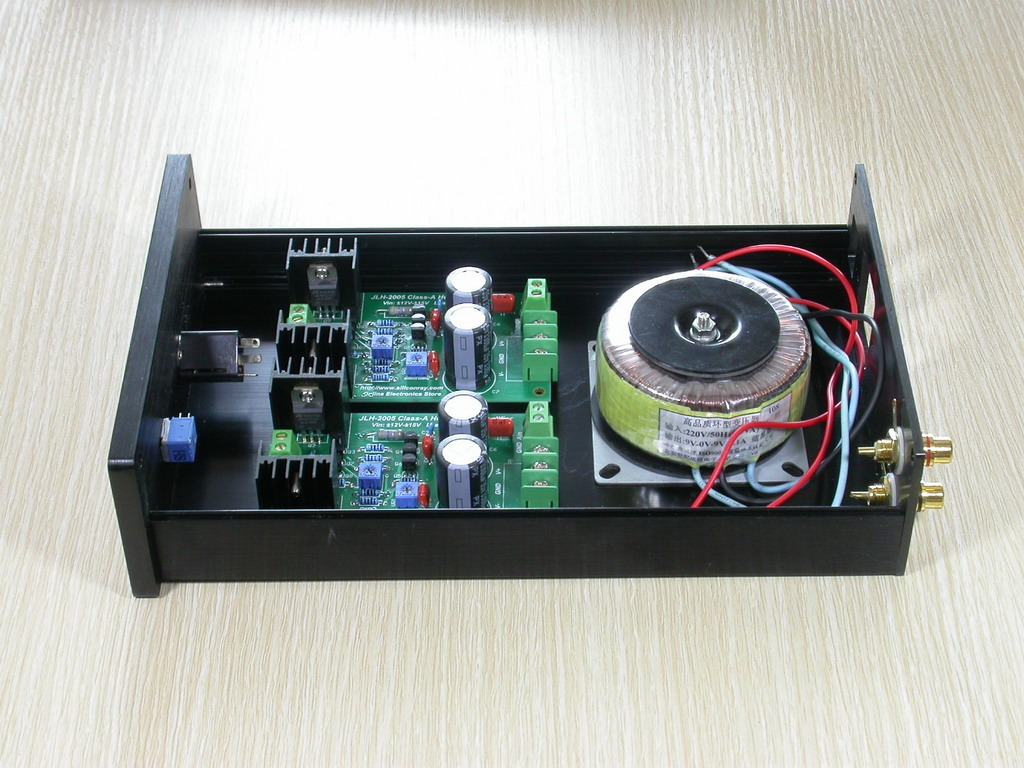
RE1506 is the ideal enclosure for the headphone amp. One 20W transformer, 2 board, RCA connector, ICE connectors, potentiometer, 6.35mm jack and switch can be easily fitted into it without any mod. There's still enough room for a small power board with a rectifier and 2 big caps.
dual 9V toroid transformer is also available for only $18.
dual 9V toroid transformer is also available for only $18.
Can anyone advise the best voltage to use with 8ohm speakers? These boards are for a single rail supply only and not split rail?
What are the variable resistors for? Dc offset?
Is there a specified adjustment proceedure on start-up?
What are the variable resistors for? Dc offset?
Is there a specified adjustment proceedure on start-up?
This is a headphone, not speaker amplifier.
They work on +-12V.
One trimmer for offset an one for bias.
If you want a speaker amplifier look at the JLH class A thread. I think that siliconray offers free boards for them too.
They work on +-12V.
One trimmer for offset an one for bias.
If you want a speaker amplifier look at the JLH class A thread. I think that siliconray offers free boards for them too.
Hi everybdy
Managed to finnish the 2 board but I have to small issues...
First is the bias and off set are not steady, they change up and down (from +/-0.00 to +/-30-40 mV (offset) and from 150mA to 220/230ma (bias) for no reason.
The second one is, if I touch the heatsinks the offset changes +/-20mV.
All the components are the ones on the schematic, R10 is 0.47Ohms and output transistores are the 2SC2238
Power supply is +/-12V regulated.
Any Ideas ?
Ric
- Status
- Not open for further replies.
- Home
- More Vendors...
- Siliconray Online Electronics Store
- ★★Free JLH Hifi Headphone Amp PCB, 0.008% THD★★