Hi,
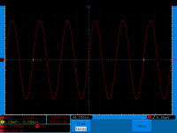
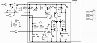
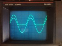
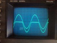
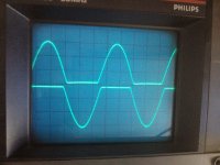
i need your help. I have a clone of fp10000q on my bench with a strange problem. On channel 3 when there is any signal it immediately starts cliping, the VPL/Clip LED come on and the output is low and distorted. I have checked the output with scope, you can see photo of good channel and bad channel. I looked the board for some burned resistors, measured all capacitors and everything seems fine. The problem is on the amplifier board, i tried switching the outputs from pre amplifier board and the problem was still on this amplifier board. Can you please direct me on what to look for or did someone have a similar problem that he solved out?
Thank you
Attachments

I found some schematic online, power supply is common for all four channels. Its labgrupen class TD so its more switching than linear i thought.
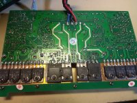
I have one of these clones and the PC board is pretty darn similar to the Lab Gruppen schematic.
"Class TD" is really Class AB with a tracking switching power supply for each rail. Looks like the negative supply is failing to track on the bad channel. That should give you a place to start. The rails from the main power supply are +/-150 VDC or more, so be careful!
"Class TD" is really Class AB with a tracking switching power supply for each rail. Looks like the negative supply is failing to track on the bad channel. That should give you a place to start. The rails from the main power supply are +/-150 VDC or more, so be careful!
Labgruppen make updates, I think we dont know which circuit they make or modify in chiense Factory
Isnt it possibile to get schematic from chinese factory or aftersales replacemt boards ?
Normally they sell boards to change the faulty channel
Isnt it possibile to get schematic from chinese factory or aftersales replacemt boards ?
Normally they sell boards to change the faulty channel
So, it looks like the problem is in PWMNATD board on the channel board. In schematic this board is shown as U5 without its schematic.
So, it looks like the problem is in PWMNATD board on the channel board. In schematic this board is shown as U5 without its schematic.
PWMNATD, is this TD driver down converter circuit
which makes the rail switching ?
yes, it's pulse drive the opto to switch main fetPWMNATD, is this TD driver down converter circuit
which makes the rail switching ?
yes, it's pulse drive the opto to switch main fet
want see drive circuit,....reverse engineering possibile ?
Does somebody know switching frequency in FP series ?
Apex have in TD1800 about 50 khz

As I said the Td1800 does not work well because the PCB design is not correct.
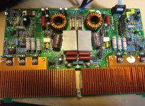
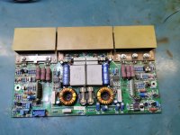
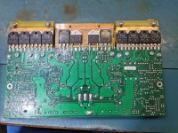
I attach photos with a Yamaha PCB diagram designed by me, it works perfectly as shown in the pictures.
I attach photos with a Yamaha PCB diagram designed by me, it works perfectly as shown in the pictures.
Attachments
At rest the frequency is 60khz, and when the power is increased, the frequency increases to several hundred khz.
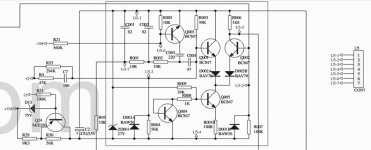
The schematic of pwmnatd and pwmpatd.
I find this, in mine original LAB GRUPPEN.
Attachments

It seems that this PWMNATD is failing often. I have one ORIGINAL LAB.GRUPPEN FP10000Q on my bench, where on one Channel, the U5 board has already been repaired. The amplifier though came into the repair shop as the other channel is failing and as I'm now figuring out it is most probably for the same reason as the one that has already been repaired.
So I soon found out that the main suspect was the PWM board as the Negative PWM was working intermittently, and when it died out the distortion and channel PEAKING symptoms (as described above) appeared.
So I first replaced the U5 board with one of the good A25TD14 amplifier boards and wasn't sure if this solved the problem. Now I soldered the presumably bad U5 board to the "known good" A25TD14 amp board and it is exhibiting the same issues. Therefore I would 99 % say that the problem is in the PWMNATD board.
My question: Has anyone pinpointed what is failing on the PWMNATD board since the fault seems to be repeating across the products?


Have a good one.
Miky
So I soon found out that the main suspect was the PWM board as the Negative PWM was working intermittently, and when it died out the distortion and channel PEAKING symptoms (as described above) appeared.
So I first replaced the U5 board with one of the good A25TD14 amplifier boards and wasn't sure if this solved the problem. Now I soldered the presumably bad U5 board to the "known good" A25TD14 amp board and it is exhibiting the same issues. Therefore I would 99 % say that the problem is in the PWMNATD board.
My question: Has anyone pinpointed what is failing on the PWMNATD board since the fault seems to be repeating across the products?
Have a good one.
Miky
Attachments
- Home
- Amplifiers
- Solid State
- FP10000q clone - clipping channel