A constant V drop between the gates is quick and easy, but the price is the class-AB style switching. Maybe something non-linear could be deployed for the VAS, like a CCS that's slightly modulated with full-wave rectified audio? In principle, the gate voltage would be at a minimum in the middle, and increase slightly at both extremes, a la cube-law class A.That was probably me 😀
The idea is intrinsically sound, but since then I've seen that crossover distortion seems to be a bigger problem.
Or SRPP? A MOSFET with gain on one half, and an Aleph-like negative resistance / modulated CCS for the other half. It sims well, but it's a bit fiddly. With a double Sziklai push-pull arrangement for the CCS (on mobile so I can't attach a pic right now) that's 5 transistors already. But the lower half could theoretically be a SIC JFET, using a battery in series for the negative voltage.So in Class A, perhaps with the top MOSFET in a current source role and the lower MOSFET doing the work (or swapped roles), it would be nice - but then Voffset would really need some feedback.

I must publish this.
It is the most nice squarewave I have seen.
Notice: 20kHz square

It is the most nice squarewave I have seen.
Notice: 20kHz square
I like the overall flow and intent of this design, and I think it is well worthy of discussion and suggestions, which is what I understand the forum's intent to be. Of concern to me is the bias setting pot on the output mosfets. I always ask myself, "What could go wrong?" The most likely failure mode (and I have seen this happen often in sensitive measurement and instrumentation systems) is that the wiper fails as an open circuit. When this happens, the bias on the n=mosfets will go to a maximum, and may lead to excessive current flow before the system can shut down. I am experimenting with using a shunt regulator in this spot, an AZ431L.
https://www.diodes.com/assets/Datasheets/AZ431L.pdf
I am not sure how it will work out yet, but it can be configured such that if the pot wiper opens up, the bias voltage will be minimal.
I think that one of the earlier posts was spot on in that it is exciting to explore minimalist topologies just to see how far they can be squeezed. I am not asserting that they are always the best possible, but is also not clear that an amp with 20 transistors is 5 times better than one with 4! Besides, experimenting is fun.
Good luck with it.
On my MOSFET circuit I simply added a red LED there, across the pot, along with a 150n cap.The most likely failure mode (and I have seen this happen often in sensitive measurement and instrumentation systems) is that the wiper fails as an open circuit.
I was pulling 6.2mA so that's about 2V on the LED. In normal operation the LED is completely off.
Ref: https://www.diyaudio.com/community/...ga28f-construction-thread.257488/post-7644501
That is a good idea. I will add such a resistor.I will add one 1K/2W resistors from negative side of C6 to ground line , just to keep that coupling cap fully charged in the case that speaker cables was from some reason disconnected and later connected again.
It is of course possible.@lineup Would it be complicated to rework the proposed scheme to +/- 20VCC to avoid capacitor C6 at the output of the amplifier?
In fact I have another amplifier with dual supply.
Has the benefit of lower PSRR of the input.
To correct DC-offset it means addition of a current source to the source of JFET.
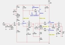
Here is the dual supply version.@lineup Would it be complicated to rework the proposed scheme to +/- 20VCC to avoid capacitor C6 at the output of the amplifier?
I added one current source JFET U5.
This version performs identical to the version in first post.
But the PSRR should be better thanks to the input.
FIVEFET it is with this version 🙂
Attachments

There was a little error in the previous schematic.
C7 should be connected to Ground.
Here is the corrected.

C7 should be connected to Ground.
Here is the corrected.
Well you can put all the transistors in a high-voltage opamp, LTC6090-5 for instance...Sometimes I look at wonderful creations, and then count 20+ transistors, at which point my head feels fuzzy and I feel there must be a better way
Personally, i preffer cap coupled amp. Or pre. I just feel more comfort being cap protected. I know this is not high current classA amp, but still, without servo there maybe some dc before it settles.
If i were to build this amp, it will be cap coupled. Just in case analog-sa is right and it will overheat, go to nuclear meltdown, and create black hole. We do not want that.
Besides, i am on vacation.
If i were to build this amp, it will be cap coupled. Just in case analog-sa is right and it will overheat, go to nuclear meltdown, and create black hole. We do not want that.
Besides, i am on vacation.
I've never been keen on opamps, it's a weakness of mine 😀opamp
I use a speaker protector on my Krell clone. It works well as I found when testing it into a dummy load and of course there are fuses in the supply rails.Personally, i preffer cap coupled amp. Or pre. I just feel more comfort being cap protected. I know this is not high current classA amp, but still, without servo there maybe some dc before it settles.
If i were to build this amp, it will be cap coupled. Just in case analog-sa is right and it will overheat, go to nuclear meltdown, and create black hole. We do not want that.
Besides, i am on vacation.
Fuses on power supply are of course a must in every case, but they are not speaker protection.
Speaker protection with dc detection is way better, but it adds complexity and additional contacts. Still, i am ok with the cap in signal path. In tube pre caps are a must. There are plenty of cap coupled amps from Mr. Nelson which sounds great.
Speaker protection with dc detection is way better, but it adds complexity and additional contacts. Still, i am ok with the cap in signal path. In tube pre caps are a must. There are plenty of cap coupled amps from Mr. Nelson which sounds great.
I plugged the dual supply version into TINA (with slight mods but mostly the same).
It seems a bit too dependent on ideal capacitors, and trimmers that can be micro-tuned to a fraction of a percent.
C7 looks like it can be removed altogether.
In my version if U1 is increased from 20°C to 40°C, Vout moves by about 150mV. Therefore the single supply version seems more practical..
It seems a bit too dependent on ideal capacitors, and trimmers that can be micro-tuned to a fraction of a percent.
C7 looks like it can be removed altogether.
In my version if U1 is increased from 20°C to 40°C, Vout moves by about 150mV. Therefore the single supply version seems more practical..
Here is the current version with single supply.
Not much is changed from the first post.

Not much is changed from the first post.
I have done a few headphone amps that use a capacitor couples output, and one thing that I "threw in" was a small relay connected directly across the output to ground, with a small, i.e. 10 ohm or so, resistor in series with the contact. The coil was wired with a time delay of a few seconds to allow the circuit to stabilize before opening the contact. This kept the output at ~0 volts during the startup and minimized thumps at turn-on. a Simple 555 timer can do the trick remarkably well. R20 above is also an excellent idea.
Have you done any tests in simulation with stepping parameters, such as the value of R4, or other circuit tolerances to see how sensitive the design is to component variation?
Multisim has a parameter sweep tool that helps with that.
Have you done any tests in simulation with stepping parameters, such as the value of R4, or other circuit tolerances to see how sensitive the design is to component variation?
Multisim has a parameter sweep tool that helps with that.
- Home
- Amplifiers
- Solid State
- FOURFET - 16 Watt Poweramp with 4 only FET Transistors