Bias is 275mA in the MOSFETs. So, it works in Class A a bit over 1 Watt. Rest is Class AB.
There is a clipping protection.
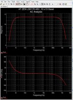
The distortion is not the lowest, but still on the low side. THD 0.004%
Bandwidth is 1.5 MHz. Thanks to the current feedback.
Could be a Toroidal Transformer 2x15VAC and a rectifier for the 40 Volt single supply.
A fun little build for those who want listen to FET sound.
16 pure FET Watt.

There is a clipping protection.
The distortion is not the lowest, but still on the low side. THD 0.004%
Bandwidth is 1.5 MHz. Thanks to the current feedback.
Could be a Toroidal Transformer 2x15VAC and a rectifier for the 40 Volt single supply.
A fun little build for those who want listen to FET sound.
16 pure FET Watt.
Last edited:

Here you can buy the 4 transistors needed.
LSK170B:
https://www.mouser.com/ProductDetail/Linear-Integrated-Systems/LSK170B-TO-92-3L-BK?qs=T%2BzbugeAwjjZsjTzJGs9IA==&_gl=1*4tdelp*_ga*NzM1MDY3NDIxLjE2OTU4MzExMDY.*_ga_15W4STQT4T*MTcxMTk3NzUwMS40MS4xLjE3MTE5Nzc3NTQuNTQuMC4w*_ga_1KQLCYKRX3*MTcxMTk3NzUwMS4xNS4xLjE3MTE5Nzc3NTQuMC4wLjA.
IRF9610PBF:
https://www.mouser.com/ProductDetail/Vishay-Semiconductors/IRF9610PBF?qs=cvaI6ThkwxtWoLkQbU/dsA==
ECX10N20-S:
https://us.profusion.uk/int/ecx10n20-s
ECX10P20-S:
https://us.profusion.uk/int/ecx10p20-s
431 Views and only 2 posters.
This means I have managed very well.
People come and look but can not find any issue with the amplifier.
This amplifier is most probably 100% perfect.
Best circuit I have done 🙂
This means I have managed very well.
People come and look but can not find any issue with the amplifier.
This amplifier is most probably 100% perfect.
Best circuit I have done 🙂
In my humble opinion, every circuit that is exposed in the forum should have a broad characterization of all its parameters. This includes, among many things, frequency analysis, transient analysis, stability analysis of polarization parameters, analysis of power noise rejection with frequency, analysis of distortion spectrum with level and frequency, sizing of all its components, etc. Many times, an incomplete simulation does not tell the whole truth that a real test of the circuit could reflect. The results are likely to be far from a very simplified simulation.
Best regards
Best regards
Last edited:
I'm still in Awe of the brilliance, so not commented yet 🙂This amplifier is most probably 100% perfect
I do like the low transistor count. Sometimes I look at wonderful creations, and then count 20+ transistors, at which point my head feels fuzzy and I feel there must be a better way 😀
Switch on thump... is a thing... but it could easily be a dual rail. If using a capacitor on the output - surely a single ended current sourced Class-A output is an interesting way forward?
I'd isolate the driver section with diodes..
I like the input FET, I like the MOSFET VAS bit, and the output FETS are nice..
I'd want a bit more voltage, in class AB.. the FET limits that a bit, but perhaps that could be finessed, current sources would be bolt-on extras - but the control loop is remarkable small, which means it should repond well to the NFB..
So I like it, it's an inspiring base for tweaks 😀
How does the design behave during startup and shutdown? Simulated?
C6 is a challange - also what capacitor is connected after the rectifier?
It should be of about the same value.
Can you specify the voltage requirements of all the capacitors?
Have you considered thermal stability, and if how?
C6 is a challange - also what capacitor is connected after the rectifier?
It should be of about the same value.
Can you specify the voltage requirements of all the capacitors?
Have you considered thermal stability, and if how?
Distortion is an interesting thing. I have built low distortion and high distortion JFET power amps and find that they are both enjoyable, although in different ways.
I do simulations in LTspice and find that it is useful for checking that the design is feasible and worth trying out, but actual performance will vary. Sometimes, the real thing has higher distortion, and sometimes it has lower distortion. Varying the operating points will produce different results as well and this is optimized through actual testing. The distortion profile can change with different operating points, and you may not want lowest total harmonic distortion, but rather 2nd harmonic instead of higher harmonics dominating.
I do simulations in LTspice and find that it is useful for checking that the design is feasible and worth trying out, but actual performance will vary. Sometimes, the real thing has higher distortion, and sometimes it has lower distortion. Varying the operating points will produce different results as well and this is optimized through actual testing. The distortion profile can change with different operating points, and you may not want lowest total harmonic distortion, but rather 2nd harmonic instead of higher harmonics dominating.
How about adding a photo of the PCB since it's construction affects performance.In my humble opinion, every circuit that is exposed in the forum should have a broad characterization of all its parameters. This includes, among many things, frequency analysis, transient analysis, stability analysis of polarization parameters, analysis of power noise rejection with frequency, analysis of distortion spectrum with level and frequency, sizing of all its components, etc. Many times, an incomplete simulation does not tell the whole truth that a real test of the circuit could reflect. The results are likely to be far from a very simplified simulation.
Best regards
That is correct. There is no PCB yet.
But it is free for someone to design a PCB.
Then we can build.
But it is free for someone to design a PCB.
Then we can build.
Looks great on paper, but maybe a bit too simple?
A couple of ideas:
--could the JFET Vds be clamped a bit better with a cascode above it? And should the cascode voltage be referenced to the input or to the source below?
--Add a Sziklai 'slave' to the JFET?
--Cascode the IRF, clamping Vds so the gain stage doesn't see such huge voltage and power swings? My guess is that this is one place where the simulations are wrong because they assume a constant room temp.
--Reconfigure R18-R19 as a trimpot to vary the inner feedback?
In another thread someone suggested taking the main feedback line from a trimpot wiper between the MOSFET gates, instead of from the output. This seems like it could have interesting implications. The power MOSFETs usually look like their gate capacitance is being charged and discharged at "maximum velocity" (limited by some combination of series resistance, slew rate, and saturation of the VAS), and seems to have potential for huge hysteresis whenever the input signal changes direction. So, are we more concerned with distortion from the output stage itself, or from the VAS being uncontrolled? Your design already takes a part of the feedback from the VAS in a fixed ratio, but it would be interesting if it could be safely trimmed, and possibly get rid of the 220uF cap.
That was probably me 😀In another thread someone suggested taking the main feedback line from a trimpot wiper between the MOSFET gates, instead of from the output.
The idea is intrinsically sound, but since then I've seen that crossover distortion seems to be a bigger problem. So in Class A, perhaps with the top MOSFET in a current source role and the lower MOSFET doing the work (or swapped roles), it would be nice - but then Voffset would really need some feedback.
As this feedback loop is so short, I think a CCS Class A version with GNFB, 10-15W with soft clipping could be a real star.
Ideally a CCS class A in the middle with Class B for the loud bits would be perfect, but I'm not sure how to do that. The CCS Class A has the benefit of less heat, IIRC, than a simply overbiased class AB.
They'll overheat in this circuit. And then you will have less than plenty😀How about irfp240/9240 as outputs? I know, they are not laterals. But i got plenty.
At less than 0.3A? Assuming proper heatsink, they will not. But whatever...you seems to consider me an idiot. Fine.
This is why the Noir headphone amp appealed to me (0ne small signal darlington and one mosfet) and I wasn't disappointed.I'm still in Awe of the brilliance, so not commented yet 🙂
I do like the low transistor count. Sometimes I look at wonderful creations, and then count 20+ transistors, at which point my head feels fuzzy and I feel there must be a better way 😀
.....
- Home
- Amplifiers
- Solid State
- FOURFET - 16 Watt Poweramp with 4 only FET Transistors