Had to give my simplistic NPN-version another try. Used devices from LTs std library.
Checked Ken´s with 1V/120Hz ripple and got 0,5mV out, mine got 1,5mV.
About distortion they are on par with both having 2nd order dominating.
No problems with temp on any of them.
Checked Ken´s with 1V/120Hz ripple and got 0,5mV out, mine got 1,5mV.
About distortion they are on par with both having 2nd order dominating.
No problems with temp on any of them.
Attachments
OK, but we are getting WAAAY beyond 4 transistors now.
There has to be a simpler way to correct a small offset.
Whats the op-amp U1 for?
Why is R14 on Q8 collector, instead of Q9 emitter?
I see regulated current diverted to one or the other
output bases, but what regulates quiescent in hot
output totem if current gain begins to run away?
There has to be a simpler way to correct a small offset.
Whats the op-amp U1 for?
Why is R14 on Q8 collector, instead of Q9 emitter?
I see regulated current diverted to one or the other
output bases, but what regulates quiescent in hot
output totem if current gain begins to run away?
Last edited:
Whats the op-amp U1 for?
Why is R14 on Q8 collector, instead of Q9 emitter?
I see regulated current diverted to one or the other
output bases, but what regulates quiescent in hot
output totem if current gain begins to run away?
Hey Ken,
From my previous post:
Adding the servo (and in this case a cap) can be a possible fix.
Just remove the ground-connections add a cap and connect to the amp instead.
About tempcomp it looks great. Don´t know though if both BJTs in the CCS needs to be on the heatsink. Haven´t dug deeper into this since I copied it from the JLH site.
The temperature behaviour looks OK in the sim because Q12 and Q9 are kept at an identical temperature throughout, but in the real world, it will instantaneously run away.
I find Ken's circuit interesting, because it differs significantly from the same old designs, rehashed thousands of times with minor modifications.
I am pretty sure it has a great potential, there is just a small detail to iron out, it's the second harmonic thing.
The circuit is functionally symetrical, which means it has the capacity to cancel most of the even order distorsions.
there remains to find the root cause of this asymetry and to eliminate it.
Was about to edit when the diyaudio-server went down an hour ago.
Anyway tempcomp is negative from 2,2A to 1,8A going from 25 to 100 C when Q12 is on the heatsink. With only the output devices on the sink we get 2,243A to 2,260A.
Built the original JLH 10W Class-A in the 70´s. Totally stable with no tempcomp whatsoever and only the output devices on the heatsink.
Anyway tempcomp is negative from 2,2A to 1,8A going from 25 to 100 C when Q12 is on the heatsink. With only the output devices on the sink we get 2,243A to 2,260A.
Built the original JLH 10W Class-A in the 70´s. Totally stable with no tempcomp whatsoever and only the output devices on the heatsink.
Last edited:
If I gotta use three parts to build a voltage
reference, might as well be an adjustable one...
If I gotta bias my input transistor, might as
well fix the voltage offset while I'm at it...
This sims much better without 600 ohms in
the signal generator. I just wanted to prove
to myself the 1000x current gain was real.
reference, might as well be an adjustable one...
If I gotta bias my input transistor, might as
well fix the voltage offset while I'm at it...
This sims much better without 600 ohms in
the signal generator. I just wanted to prove
to myself the 1000x current gain was real.
Attachments
Member
Joined 2009
Paid Member
The Elvee fix looks very familiar - I think it's the P. Taylor fix, Wireless World 1973 (referenced somewhere on tubecad) 😕
Yar canna fix 2nd in that way, me bucko... Juma proves why.
But keep tryin. I still don't know exactly why the 2nd doesn't
cancel with equal resistors. But its probably just the emitter
of Q1's non-linearity you are observing.
--------------------------------------
The sum of voltage across R1+R3 is held constant in paraphase.
I'm messin around with class AB, by puttin Schottkys in series
with R1 and R3, to make a constant sum of non-linear devices.
This trick wouldn't work if R1 and R3 were greatly different...
The value of R2 also seems critical in achieving equal current
swings in the balance.
This post references to Juma's most recent Q and R numbers
rather than my own. Just now realize they are slightly different.
Last edited:
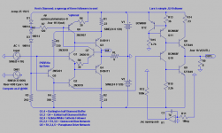
This is my idea of how to use the "JLH-follower". By setting the driver with a little offset you get zero out.
The plot is for output-voltage and current through R12 at onset of clipping.
This is just a concept, feel free to adjust the driver to work IRL, if possible😉.
The plot is for output-voltage and current through R12 at onset of clipping.
This is just a concept, feel free to adjust the driver to work IRL, if possible😉.
Attachments


By making the ratio of R10 to R11 exactly 2, the second harmonic practically vanishes.
Hey Elvee,
Tested this with the NPN version and there the second-order is still dominating. Question is if that is negative. In the tubeworld chasing odd-order is the main concern.
I got rid the 2nd harmonic by lessening the 390ohm and replacing the
missing voltage drop with yet another transistor (strapped as a diode).
This fakes some I to V nonlinearity at the collector more similar to the
emitter circuit.
The weakness with JLH circuit is that drive current is held constant.
Way more drive current than needed for the quiescent state, just
to insure sufficient drive to swing rail to rail. I'm assuming this must
make the output transistors idle hotter too?
I still don't get the point of R12 in the collector?
Last edited:
Member
Joined 2009
Paid Member
This is really nice work !
I've been designing a JLH front end driving a Taylor follower and see a lot of commonality between that and the direction this thread is now heading in. I've also ended up with a transistor as a diode in use to reduce distortion. Where I've used it pushed down H3 but not H2. I'll have to try this H2 trick next.
I hope to have something build this winter.
Revintage - that front end looks very close to one of the JLH pre-amps too - have you build something like this before and if so can you comment on it's performance ?
I got rid the 2nd harmonic by lessening the 390ohm and replacing the
missing voltage drop with yet another transistor (strapped as a diode).
This fakes some I to V nonlinearity at the collector more similar to the
emitter circuit.
Initially, I had used different values for the collector and emitter resistors of the translator to compensate for series parasitics in the emitter and parallel loading in the collector. A E12 step was clearly too much, E24 would have been more accurate.
But instead of balancing the paraphase you can go the opposite direction and get good results too: here is an example with R6 practically shorted: H2 is below the ppm, and the overall THD is 15ppm. Unfortunately, it affects the dynamic as juma noticed, and is therefore not usable.
It is interesting to look at how well the paraphase manages to keep the sum of currents constant: the red trace shows the results, and it is pretty bumpy.
The green trace is the dynamic hfe of Q4, and it shows substantial variations, a 1 to 5 ratio, and also an asymetry near the top, meaning there are dynamic effects too.
For me, all this means the D45H11 are stretched beyond their limits, and most of the unwanted effects could eliminated by substituting half-decent devices.
Attachments
Hey Ken,
R12 (0,0001ohm) is just for monitoring the quiescent current in Spice. The buffer is pure push-pull Class-A and current can easily be calculated. The sims indicate overcurrent giving better results though.
R12 (0,0001ohm) is just for monitoring the quiescent current in Spice. The buffer is pure push-pull Class-A and current can easily be calculated. The sims indicate overcurrent giving better results though.
Elvee,
If the present models isn´t sufficient why not use some that are common in audio like the 2SC3281 I use.
Bigun,
I´m into tubes and have just started to do theoretical models of modern sand stuff. But I have a descent ground to stand on since I studied electronics in the beginning of the 70´s. In other words I haven´t built this design IRL😉.
Last edited:
Member
Joined 2009
Paid Member
Well I'm most interested to see how your design turns out - I have already 'adopted' your version of the JLH into my current simulations and love it.
The 70's --- ah, lots of music from those days to motivate your efforts.
The 70's --- ah, lots of music from those days to motivate your efforts.
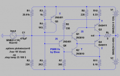
Have been running som temp simulations on Ken´s and my follower.
By exluding some of the devices from the heatsink a quite good behaviour with just a few mV drift can be reached. The T-marked devices should be on the heatsink the 25´s should be kept at constant temerature. My needs some kind of extra comp as offset is ca 60mV from 25 to 100 degrees C.
By exluding some of the devices from the heatsink a quite good behaviour with just a few mV drift can be reached. The T-marked devices should be on the heatsink the 25´s should be kept at constant temerature. My needs some kind of extra comp as offset is ca 60mV from 25 to 100 degrees C.
Attachments
http://www.6moons.com/industryfeatures/zen/plh.pdf
Highlee interessant....
Seems John Linsley-Hood abused a Sziklai of PNP + NPN to drive NPN.
At first I thought JLH maybe an entirely different theory of operation?
Cause I see he's got NPN stuck between NPNs?. But his PNP up front is
working exactly like mine in the middle, so treating his Sziklai input as
as one big PNP, its the same circuit.... Also, JLH opted to compute a
voltage gain within his follower, at cost of opening the diamond to DC
offset.
Main weakness of the classic circuit seems to be in stabilizing the bias.
Now, as I've pointed out recently: JLH seems to be splitting a constant
drive current, rather than maintaining a constant output current in sum.
Thus the output transistors must idle way hot in the quiescent state,
to make sure there enough drive current in reserve to swing the peaks.
Where mine don't look like JLH: I got a White Cathode Follower style
splitter maintaining a sanity check over DC bias and balance of the
JLH splitter. Doesn't need a boatload of CCS to keep it in check. The
sum of output currents is held to a constant, rather than the drive.
Excess drive currents, not needed by the output during quiescence,
are bled off. So it isn't ever likely to run away...
Last edited:
- Status
- Not open for further replies.
- Home
- Amplifiers
- Solid State
- four transistor emitter follower (diamond buffer) as power output stage?