I tried ribbon replacement with a pair of Fountek NeoCD3.0 ribbons. Out came the original laminated ribbons and in went some true corrugated aluminium foil ribbons using standard household foil. A few things surprised me, firstly how easily torn the laminated foil is (it barely feels any stronger than pure foil), also how similar the two responses are.
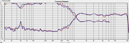
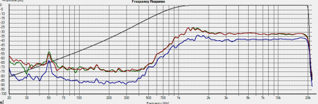
Attached is a measurement of new/original. Blue = original laminated foil. Red = corrugated pure foil. As both new ribbons measure pretty much identically to each other just one is shown here. I was hoping the the large hump at then bottom end making for awkward Xover design would be flattened out with the new foil but unfortunately it isn't, and secondly, with the corrugated foil there is a more pronounced dip around 5.5kHz. The measurements were taken with the unit on the floor facing up which is not ideal but good enough for a relative comparison between the two I would think. Plots are smoothed to 12/octave
I'd like to reduce the depth of that 5.5kHz dip if at all possible...but I wonder how.
Tim
Attachments
Last edited:
I have done similar many times to that exact driver and have been involved for many years in ribbon development.
Founteks claim of " laminated " ribbon I am not too sure about. I have put their ribbon elements under a scope and torn them apart a number of times. I cannot see any evidence that it is actually a laminated structure.
I have built countless laminated and foil only ribbons of many different materials and construction variations and have developed proprietary methods in this area, so I do have a bit of experience here.
I cannot say beyond all doubt that they are not laminated BUT I cannot find the evidence for it.
The ribbons used in these designs are somewhat thicker foil ( .0005" in this design) than is used in some others and that is likely the reason they hold up a little better rather than any reliability benefit from laminating. Also this is why good old kitchen foil worked so similarly as it is usually about .0007" thick. You should see a drop in impedance of an ohm or two, from 8 to about 6 ohms and a small drop of about 1-2 db at 20kHz
as for the large hump in response. This is due to the ribbons back chamber, not the foil. The chamber on these designs is very small and results in a helmholtz resonance determined by the volume of that chamber and the size of the ribbon slot. No way around it when the chamber is this small.
Unfortunately it as you say makes a clean crossover very difficult down there , However these types of ribbon designs have poor distortion and reliability issues below about 2.5 kHz anyway so best to cross higher.
As for the dip at 5.5 k. This could be a couple of things. It may be simply a diffraction issue as you really need to flush mount the ribbon on a large smooth baffle to make useful measurements. I would do that first and dont underestimate how important smooth flush mounting is to measurments. Very small ridges can easily show up. AND when measuring stretch out the graph as much as possible and use something like 1 or 2 db/div rather than 5. This way can really see whats going on.
The other possibility is your corrugations. All corrugated ribbons tend to have issues with a resonance somewhere between 2 and 7 kHz depending on size shape of corrugations and weight of foil. You can test this by stretching the ribbon out a bit and see if the dip moves down in frequency. If it does then its at least in part due to the corrugations. So called "flat" foil designs are the easy way around this issue BUT they have other issues to deal with
Now I assume you mean the sharp dip at 5.5k here. On another note and not easily seen in your measurement is the long rounded hump up in response between about 5 k and 15k. This is partly to do with the effect the ribbons slot size has on the response and to flatten out you will need a RLC trap circuit.
Last edited:
Lowmass
Thank you for you very comprehensive reply.
Your comment on the reduced impedance is interesting as I wouldn't have expected that. I shall measure and compare with the original. I'll remeasure the response on a baffle too.
I do wonder about the corrugations and I notice my Aurum Cantus G2si has a more complex corrugation pattern (corrugations within corrugations) on top of a fine 'textured' background, you could almost call it three layers of corrugations. Not easy to replicate without specialised equipment I guess, though I will try adding the background texture to my next attempt to see what happens, possibly stretching a little tighter too.
Tim
Lowmass
When I noticed how easily torn Fountek's laminated element was and how similarly it measured to my corrugated effort I started wondering if a flat ribbon made of standard foil might actually work. Possible issues I can think of....
1. Stretch/sag over time.
2. Break...but from what, metal fatigue from the miniscule movements of normal use?
...but are these real enough issues to rule out such use, or perhaps I'm missing other reasons not to consider this. Any thoughts would be much appreciated here.
Tim
In ribbon design flat is the easy way to avoid the resonant issue seen with corrugations.
Flat is not bad at all and done well it can be quite good. Sounds like Aurum has done some work to try and soften this effect BUT my experience says you cannot eliminate it when using a corrugation in a simple foil only ribbon.
Sometimes you can just use smaller sized corrugations and both lower the break point and soften it a bit, but generally flat is the best at avoiding it.
YES you can do a flat with the kitchen foil. But with typical ribbons this size you really cant cross low as the distortion and reliability is poor.
Founteks soft silicone rubber "clamps" at the ends of the ribbon is an elegant design that automatically puts a self adjusting tension on the flat ribbon at install, and takes care of problems with cracking, but it still cannot handle the stress of a low crossover and again even if it could these simpler ribbon element constructions, flat or corrugated, have a fundamental issue that results in a strongly rising distortion profile below about 2000 hertz.
I have built ribbons along the RAAL design. The biggest difference between your Fountek and the RAAL is mostly ribbon mass. There are other details in their design that people may say are a big deal but I have built countless versions intermixing ALL these details and the ribbon mass is the biggest difference IMO. The RAAL foil is about 1/3 the mass of that used in the Founteks. Many people think/ believe? that is a game changer. I can say this much, using the ultra light ribbon has advantages and they can be quite good, BUT it is not the last word in ribbon development IMO. My work tells me that the more important part of the music spectrum, say between 1k and 5 k is better done with more mass BUT with some tricks to get it to behave better.
Last edited:
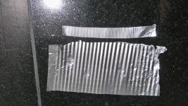
Thank you again, very interesting. I have made a test piece using corrugations 1/3 the size I used before so this will be 'mark 2'. The picture shows this above my original. I also wondered about corrugations interspersed with flat sections along the same diaphragm but as this would lose some elasticity compared with standard corrugation I'm not sure it's a good idea.
Your comments on light weight ribbon diaphragms tally well with my own findings having played around with different mylar thicknesses for electrostatic panels.
Your comments on light weight ribbon diaphragms tally well with my own findings having played around with different mylar thicknesses for electrostatic panels.
Attachments
Last edited:
hmm yea interesting on the stat panel mass
When I look at the ultra low mass foils pulse response I do see a fast decay BUT the higher mass stuff IF well damped has just as fast a decay AND its also less back and forth swinging past zero crossing going on in that decay. Not as knowledgeable as I would like to be on how to interpret that but to my ears when crossing ribbons down around 500 to 1khz I like the higher mass stuff better ( again if damped right). That decision came hard as I originally started with the belief that the lowmass stuff simply had to be better. Over time my ears said something different , however I will admit it wasn't until I found a better way to damp the heavyer stuff with out simply throwing a wet blanket over the whole ribbon.
I suppose theres still the argument that the extended response of the lower mass stuff says that "technically" it must be doing a better job down below that. Well again that all makes sense in the mind BUT in years of building and listening to all the different designs Im just not sure we have enough understanding here
As far as the "elasticity" goes, I wouldn't be too concerned with that unless your trying to take that small ribbon below about 2kHz. The moves are too small to matter and the silicone terminations in that design give enough to allow flat foil
Last edited:
With finer corrugations I now have a nice flat response without the 5kHz dip and both units measure almost identically to each other so all good there BUT when measured against another untouched pair of NeoCD3s the refoiled pair have each lost around 7dB in sensitivity! The pure foil is no thicker than the laminate which I removed but I suppose it could be heavier being all metal...? Also, I made the new elements 0.5mm or so less wide than the original but would any of this really be enough to account for 7dB? I'm baffled.
YES
the ".5 mm or so" is the biggest reason
the kitchen foils are a bit heavier but not because of Founteks claimed lamination, its simply because its thicker. easy to miss that there different thickness unless have a good measuring device. I believe stock foil is .0005 inch thick and kitchen foil is .0007 inch thick ( thats for standard kitchen foil, the "heavy duty" kitchen foil can be closer to .001 inch) However its also going to lower impedance a bit so the extra mass is offset a bit by the lower impedance. Probably should only see maybe -1-2 db difference due to mass.
the shape of the corrugations also contributes. The steeper the corrugations the less sensitivity you will have compared to flat. Flat is better aligned to the magnet flux lines than corrugated. Typically I see about 1-2 db loss with corrugations depending on size/ shape. The closer to flat, the higher sensitivity will be.
The "gaps" between the ribbon and the magnet surfaces is a BIG deal ! It can easily cut 5 db or more. And getting EXACT ribbon widths = is critical to matching a pr. in sensitivity.
You can lay two layers of foil on cutting table and cut both at same time to get exact match and just keep doing it till you get exact width you want. in a small width ribbon the gap size becomes even more critical as the % gap to ribbon area is higher.
Fill the magnet gap up better ( smaller gaps) with the kitchen foil and corrugations and I guess you will be about -2 to -3 db down from stock . Use kitchen foil flat ( no corrs) and maybe -1 to -2 db down from stock foil. Fill the gap up even tighter with flat kitchen foil and may get it all back BUT at around 6 ohm rather than 8
Last edited:
I see what you mean! I've filled the gap very tightly with marginally smaller gaps even than stock and I'm back up by at least 8dB which I'd never have expected without your advice so thank you.
I've fine corrugated again this time as I stupidly lost one of the silicone inserts but in any case the idea that there's a degree elasticity/self healing appeals to me. I shall plot the impedance next.
I'd like to try thinner foil at some point so is there a known source for this, cannibalised film capacitors perhaps, or is it simply a question of purchasing a roll of a suitable thickness, assuming something can be found?
Tim
Last edited:
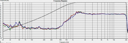
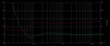
Attached, images of the two rebuilt corrugated elements (red and green trace), alongside an original stock (blue). I'm pleased with the result. The first plot has the stock unit set at a lower volume while the second has all three as measured.
Impedance plot soon but in the mean time a big thankyou to you Lowmass.
Impedance plot soon but in the mean time a big thankyou to you Lowmass.
Attachments
Last edited:
good job Tim
Nice response there.
Im curious however about the flatness of the response? That driver , as is typical to ribbons, has a hump in its response. Its a + 5 or 6 db rise from about 6kHz to 20 kHz with its peak around 12 kHz. Yet you are getting a seriously flat response through that section. Are your measurements the raw driver or maybe some EQ?
They are raw measurements as EQ would surely defeat the object of the excercise. They were made at around 1 meter from the baffle with an calibrated Behringer ECM8000 oriented at 90 degrees which I understand gives the most accurate response.
Could the flatness be due perhaps to the now reduced gap between element and magnets which is now much smaller than the original?
Could the flatness be due perhaps to the now reduced gap between element and magnets which is now much smaller than the original?
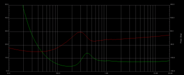
Attached are impedance plots of a rebuilt NeoCD3 with corrugated element vs a stock NeoCD3. The measurement setup was identical for both except I didn't bother mounting the rebuilt unit on the baffle (assuming it makes no difference) so measured it face up sitting on the worktop.
Both rebuilt units measure the same as each other but both over 10 ohms which is significantly higher than the stock unit. I'm puzzled by this but again I wonder if the fact that the smaller gap between element and magnet is somehow providing acoustic loading. This is just a stab in the dark though.
Both rebuilt units measure the same as each other but both over 10 ohms which is significantly higher than the stock unit. I'm puzzled by this but again I wonder if the fact that the smaller gap between element and magnet is somehow providing acoustic loading. This is just a stab in the dark though.
Attachments
Last edited:
well with the mic at 90 deg I would expect to see a drop of around 5 db above about 10kHz. You may want to do some on axis measurements. Sometimes its best to do the measurements at 1/2 meter with about 3 ms gate to get everything from room out of the picture.
Also if you are using a slightly wider ribbon then the low frequency loss through the gaps may be less. All together you may have some loss at high freq due to mic at 90, and some gain at low freq due to gap fill, all resulting in the response your getting now.
As for the impedance, I would think that the kitchen foil would be thicker than the stock foil, plus if you made the ribbon a tad wider, then this should end up giving a lower impedance not higher. Strange. I doubt its anything to do with acoustic loading but not absolutely sure about that.
I have noticed in past that if you don't have near perfect connection to ribbon at the terminations you can get higher impedance AND sometimes with transformers an extended high freq response.
Very small changes in contact resistance between terminations and foil can be an issue, even showing up on distortion plots even though it sounds ok.
When I do connections I coat the contact blocks with some oil and using a 300-400 grit sand paper clean them up. I keep them wet with oil so that oxygen cannot get to the cleaned aluminum blocks. Aluminum makes oxides instantly and the oil stops that. Then when done cleaning/ roughing up contact area I wipe all the grit off with an oil soaked rag. Again idea is to get clean raw aluminum surface without oxygen ever getting to it. Also the rough surface ( very tinny scratches) now sort of cut into the foil ribbon just a bit when you clamp it all down, or in your ribbons design it uses wedges I believe. Elegant design.
Any oil will work. Ive used baby oil, cooking oil, motor oil, etc etc. Probably best to use silicone oil as it will never dry out and lasts forever but any oil will work in a pinch
Thanks again for the very interesting information. I think the suppressed resonance peak on the rebuild units is telling me something. I wonder if it's due to the elasticity of corrugations vs flat...or maybe something else. In any case I might try again with a very marginally narrower foil to see what happens with the impedance then.
Oil, that's an interesting choice. From what you say it evidently works even though oil is supposed to be an electrical insulator. I could try some silver conductive paint.
Oil, that's an interesting choice. From what you say it evidently works even though oil is supposed to be an electrical insulator. I could try some silver conductive paint.
yes the suppressed peak is interesting. Its not only suppressed but moved down in freq quite a bit. I too am wondering. Maybe its the wider ribbon closing up the gaps at the edges?? but I would actually expect it to possibly get worse or stay the same.
Again it could be contact resistance as a resistance may have a damping effect? not sure but looking forward to your find here.
Oil is an insulator BUT once two surfaces are squeezed together tight its a non issue and the anti oxidant qualities work to preserve the contact.
I did a long term study years ago on electrical connection quality and reliability in salt mining environment. Everything from low power contacts on computer components and building lighting , to high power and high voltage connections on power feeds and motor from 1 HP to 1500 HP. Both AC and DC power. Both aluminum and copper and combination of the two.
We experimented for 10 years with every know "electrical contact paste" and conductive paints. Every single one of them failed over time except pure silicone dielectric paste.
All the commercially available "electrical pastes" would dry out over time and in HID lighting environments most of them would actually harden like epoxy ether from the lights radiation or the heat.
In the end simple pure silicon dielectric paste ( a great insulator BTW") ) was by far the best. In fact even a thin coating pure silicone spray that comes in an aerosol can was great. Once a clean surface was coated with the silicone " oil" it would last forever and it was almost imposable to clean off.
) was by far the best. In fact even a thin coating pure silicone spray that comes in an aerosol can was great. Once a clean surface was coated with the silicone " oil" it would last forever and it was almost imposable to clean off.
In high current conditions ( which the ribbon connection is BTW ) as soon as the connection is even a little less than perfect there can be problems. In ribbons this can be measure with a special electrical meter BUT even distortion will show a marked rise! not sure whats going on there ha. Anyway the heat generated by the bad connection will advance the corrosion quickly and the problem just grows. Keep the connection from corrosion and there will be no problems.
The oil keeps the corrosion from creeping in from the edges exposed to atmosphere.
Ive seen motor oil last for years too but silicone "oil" is the best
Again it could be contact resistance as a resistance may have a damping effect? not sure but looking forward to your find here.
Oil is an insulator BUT once two surfaces are squeezed together tight its a non issue and the anti oxidant qualities work to preserve the contact.
I did a long term study years ago on electrical connection quality and reliability in salt mining environment. Everything from low power contacts on computer components and building lighting , to high power and high voltage connections on power feeds and motor from 1 HP to 1500 HP. Both AC and DC power. Both aluminum and copper and combination of the two.
We experimented for 10 years with every know "electrical contact paste" and conductive paints. Every single one of them failed over time except pure silicone dielectric paste.
All the commercially available "electrical pastes" would dry out over time and in HID lighting environments most of them would actually harden like epoxy ether from the lights radiation or the heat.
In the end simple pure silicon dielectric paste ( a great insulator BTW
) was by far the best. In fact even a thin coating pure silicone spray that comes in an aerosol can was great. Once a clean surface was coated with the silicone " oil" it would last forever and it was almost imposable to clean off.In high current conditions ( which the ribbon connection is BTW ) as soon as the connection is even a little less than perfect there can be problems. In ribbons this can be measure with a special electrical meter BUT even distortion will show a marked rise! not sure whats going on there ha. Anyway the heat generated by the bad connection will advance the corrosion quickly and the problem just grows. Keep the connection from corrosion and there will be no problems.
The oil keeps the corrosion from creeping in from the edges exposed to atmosphere.
Ive seen motor oil last for years too but silicone "oil" is the best
- Status
- This old topic is closed. If you want to reopen this topic, contact a moderator using the "Report Post" button.
- Home
- Loudspeakers
- Multi-Way
- Fountek NeoCD3.0 Ribbon Replacement