soulmerchant yes but if they are dry they wont filter the ripple and that will produce hum
tarzan wd40 is non conductive why shoudnt it be used?
el156
hi nice to see also a fellow portuguese here...love Portimão also, if you ever come to Porto please let me know
best regards to all
hugo
tarzan wd40 is non conductive why shoudnt it be used?
el156
hi nice to see also a fellow portuguese here...love Portimão also, if you ever come to Porto please let me know
best regards to all
hugo
A good read about WD40:
Why I don't use WD-40 on amplifier electronics | Telecaster Guitar Forum
Then try it and order new parts after the damage.
Why I don't use WD-40 on amplifier electronics | Telecaster Guitar Forum
Then try it and order new parts after the damage.
Hello MichaelSamra from Michigan,
The Concert is giving you headaches I think.
I see a small bottle with Ibuprofen....
hugobarbedo,
Don't worry though,
Dynacord amps are good designed units.
Trafo's are very robust; I never had to replace one in my life.
Nice project.
Small bottle? Hell that's a big bottle LOL. The amp isn't mine.It belongs to another gentleman on here..I wish it was mine.The only European amps in my collection are my Leaks.
Last edited:
soulmerchant yes but if they are dry they wont filter the ripple and that will produce hum
tarzan wd40 is non conductive why shoudnt it be used?
el156
hi nice to see also a fellow portuguese here...love Portimão also, if you ever come to Porto please let me know
best regards to all
hugo
Hi Hugo !
Portimão is where i work, and only went to Porto twice, is a beautifull city ! If you come here for holidays, let me know ! And good luck with the ristoration of your nice amp !
hi everyone
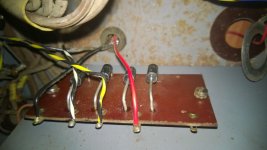
today i had a spare hour and replaced the rectifier with some new 1n5406 diodes i had laying around. they are rated 600v 3amps and peak surge current 150amps
i thought this unit had a selenium rectifier but it has a bridge of 4 si1.2 siemens diodes wich tested good on the dmm but were all badly rusted.
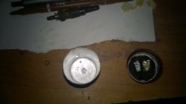
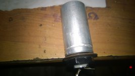
also started on repurposing the can caps
cutted them open on a place were they make now a "click-fit" and removed the guts and washed them.
fitted some 47uf old caps in place under the chassis just so i can still power the amp while new caps are ordered.
in spite this things the amp still hums like crazy....somebody told me it could be a bad tube but it hums equal on both channels. also its volume dependant and when i power it down the hum disappears and the sound is great for 3, 4 seconds before fading away
any thoughts?
tomorrow will try to take some voltage measurements etc and post
best regards
hugo


Last edited:
Ok, I just re-read michaelsamra's post to not get in trouble.. I don't think he is recommending 100uF caps so you should be OK if you keep them not too high. Films are of course always ideal ... 😉
If he goes with electrolytics he should go with the 100uf because he doesn't have to contend with a tube rectifier in the charging stage.I do this all the time on Sherwoods where I use a 35uf poly off the Gz34 and then then the next two sections I put in dual 100uf lytic and then in the phono I also go with a dual 100uf lytic..The idea is to have reserve on transient dynamics which as you well know is much higher now than when the amp was built. We have some Cds running at over 100db in some cases and that will drain a power a small lytic and hit the rail quickly.. Now if your using film caps,a pair of 50uf would be great because of the speed and efficiency of film caps. As long as you don't change the impedance of power supply by going too large like in the 700uf to a 1000uf range and higher. That would be ridiculous..
His amp is only using 64uf total and we talking the amp,preamp,and phono and that's quite a chore because he has no added decoupling capacitance or reserve and this is important now with the trash on the AC line as well as the higher dynamics in the music.If you go with films,the lower values are fine.
I'd be worried about I2R heating in the old power trafo. Using an "efficient" 35 μF. film cap. at the I/P of the B+ filter makes lots of sense to me, as the heating demon will not appear and the filter will work well. Notice the paralleled pair of 5.1 Kohm/2 W. resistors (R36/R37). The OEM B+ filter is CRC with a dual section (32 μF. each) in both the I/P and reservoir positions. A 120 μF. low ESR 'lytic from either Panasonic or Nichicon as the reservoir cap. "feels" right to me in both the energy storage and space occupied departments. If it can be "shoehorned" in, a modest cost Triad C-17X choke would improve the performance of the B+ filter. CLC is better than CRC and resistance can be used in series with the choke, to fine tune the B+ rail voltage. Provided they are within tolerance and good condition, retain the OEM resistor pair.
Nichicon's UCP2W151MHD is a 150 μF./450 WVDC 105o C. part that measures 40 mm long/18 mm dia. The part is rated for 970 mA. of ripple and 10000 hour life.  🙂
🙂
That cap. is (IMO) a prime candidate for the reservoir position.
 🙂
🙂That cap. is (IMO) a prime candidate for the reservoir position.
absolutely..A choke would be ideal and he has room.
That and the nice lytic you mention which would give him reserve he needs.
Nichicon's UCP2W151MHD is a 150 μF./450 WVDC 105o C. part that measures 40 mm long/18 mm dia. The part is rated for 970 mA. of ripple and 10000 hour life.🙂
That cap. is (IMO) a prime candidate for the reservoir position.
That and the nice lytic you mention which would give him reserve he needs.
If he goes with electrolytics he should go with the 100uf because he doesn't have to contend with a tube rectifier in the charging stage.I do this all the time on Sherwoods where I use a 35uf poly off the Gz34 and then then the next two sections I put in dual 100uf lytic and then in the phono I also go with a dual 100uf lytic..The idea is to have reserve on transient dynamics which as you well know is much higher now than when the amp was built. We have some Cds running at over 100db in some cases and that will drain a power a small lytic and hit the rail quickly.. Now if your using film caps,a pair of 50uf would be great because of the speed and efficiency of film caps. As long as you don't change the impedance of power supply by going too large like in the 700uf to a 1000uf range and higher. That would be ridiculous..
His amp is only using 64uf total and we talking the amp,preamp,and phono and that's quite a chore because he has no added decoupling capacitance or reserve and this is important now with the trash on the AC line as well as the higher dynamics in the music.If you go with films,the lower values are fine.
Ok, that is why I use film caps. But they need space which he doesn't have. I haven't used electrolytic in quite some time.
I'm cautious not to go too big in 'lytics since they need recharging after transients too, and of course that need competes with the tube. I tend to try to find out how low I can get away with.
Just my experience and personal taste perhaps. I find that these older designs can start sounding muddy and dark when the get re-capped with 3x what the original designer used..
There is a lot of trash on the lines today, but going from 33uF to 47uF might be just enough. I won't get in an argument with you and Eli over this though. 🙂
soulmerchant yes but if they are dry they wont filter the ripple and that will produce hum
You really should not be powering this up if it is in such a state. Your poor mains transformer might not survive it.
Ok, that is why I use film caps. But they need space which he doesn't have. I haven't used electrolytic in quite some time.
In our builds switching to film caps in the power supply was one of the biggest improvements we made.
dave
Hello hugobarbedo,
First get these new electrolytics in.
Use a light bulb in series with the mains to start up the amp.
If there is that hum again, Switch the amp of.
Remove tube Ro 9 and 10.
Switch on again.Still hum?
Switch of, remove tube Ro 7 and 8 and reinsert Ro 9 and 10.
Switch on again. Still hum?
Either there is still a problem in the power supply section or you have several bad power tubes or several bad cathode resistors.
Check the voltages in the power supply section.
That's at C50b, C50a, C11b, C11a.
Then at the power tubes,
Pin 7 - Anode, Pin 9 - Screen, Pin 3 - Kathode.
Do this for tube Ro7, 8, 9 and 10.
If these are all as in the schematic,
Remove RO 9 and 10.
Insert a signal in the amp, wich channel dosn't matter.
Check the signal at the din connector (at the bottom left of the schematic)
Pin 1 and 4 first (Signals A and B) - Preamps and mixers
Then Pin 3 and 5 (Signals C and D) - input to the phase splitter
But these signals are probably hum free. Why?
Because having two seperate preamp sections producing hum in both channels is very unlikely.
Let us know what your findings are.
Hi everyone
this project has been sitting for 2 years now because my child was born, i had to move into a new house and make some construction work etc
anyway the tips you gave me will be very usefull when powering the amp again because i decided to fully restore it instead of chasing the problem.
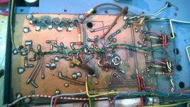
i started the work at the time of my last post and now i have the amp on the table ready for some final wiring...
it was a massive pain beacuse i had to dessolder every wire in order to remove the components to paint the chassis because some components go out to the back and some go out to the inside of the case.
i will leave photos of before and after
i replaced every single capacitor and resistor for equal value ones
although all old resistors tested good but some were very burnt
before


now


this project has been sitting for 2 years now because my child was born, i had to move into a new house and make some construction work etc
anyway the tips you gave me will be very usefull when powering the amp again because i decided to fully restore it instead of chasing the problem.
i started the work at the time of my last post and now i have the amp on the table ready for some final wiring...
it was a massive pain beacuse i had to dessolder every wire in order to remove the components to paint the chassis because some components go out to the back and some go out to the inside of the case.
i will leave photos of before and after
i replaced every single capacitor and resistor for equal value ones
although all old resistors tested good but some were very burnt
before


now


- Status
- Not open for further replies.
- Home
- Amplifiers
- Tubes / Valves
- Found a vintage Dynacord Concert EL84 amp

