
I don’t do your version of tact, I try to help fellow DIYers with factual stuff instead of the usual pointless drivel or replying to such (but the devil tempts me regularly).
Post #18, it is in english though.
Post #18, it is in english though.
Last edited:
The same Monacor line attenuator as I used before.
To get -10 dB, I switched to four Vishay dale resistors ( two for each channel ) 10K in series and 2K in parallell ( to earth ), soldered the resistors inside the amplifier at the RCA:s and the sound became much clearer , better than using Monacor.
Doing this you both get better sound and dont have to mess with the op amps. I would personally switch opamp 2 and 3 to opa1612 or opa1642 , I think those are better sounding than ne5532 .
Audiophonics is a good seller.
Well, what you did is this - you removed two points of contact resistance by excluding:
1 one RCA plug<->socket contact (removed the "banana" gain-select adaptor)
2 removed another point of contact resistance (gain-amount select switch)
... no wonder the sound is better... not to mention the better-sounding resistors you used.
So, well done.
EDIT:
The suggestion I posted in reply No. 12 would cause even less harm. However, just a touch of knowledge and willingness to trace the wires and use an ohmmeter is required, as is removing an SMD resistor and soldering another one in its place. But the end result would definitely be worth the effort.
If I knew then what I know now, I might not have gotten this preamp, it does sound nice though 😉
https://www.aliexpress.com/item/1005004049392692.html

4 RCA in, 1 RCA out, 128 steps @ 0.5dB

Add two more resistors here? Value?
What's better, preamp input or output?
How does this change the impedance?

https://www.aliexpress.com/item/1005004049392692.html
4 RCA in, 1 RCA out, 128 steps @ 0.5dB
Add two more resistors here? Value?
What's better, preamp input or output?
How does this change the impedance?
Last edited:
I learned about gain and impedance after buying. 🙄What are the signal levels of your sources and what is the input sensitivity of that Fosi? Does the Fosi work with correct volume when connected to a normal (younger than 20 years) source with built in volume control? If the answer is yes it is a fools decision to change the Fosi. You then need a preamp that has less or even no gain. A buffer, signor! Possibly you only want source selection and volume control. Choose a nice relay based version and possibly an output buffer and it is solved. You married 2 incompatible devices and now the marriage is over. Finito, there were no winners in this marriage. Let's hope there are no children.
A way better marriage is to switch over to XLR/balanced pre/buffer/source selection/volume.
Most people would just reduce the source volumes (streamer+DAC, CD player), but that would be too easy. 😉
The recommended use of these amps is directly with a DAC with volume control. XLR in and out. For example Fosi ZD3 (came out later).
V3 mono:
input impedance RCA 25KΩ (XLR 5KΩ)
input sensitivity RCA 2V (XLR 4V)
Last edited:
What most people do is what you should not do. Try to solve issues at the root or better: solve issues by not letting themselves develop. Like inserting a random gain (non standardised) block while needing low or no gain. With standardised sources and standardised power amplifier. Then wanting to handicap a perfectly fine power amplifier. It is very likely drive capability of that preamp is worse than your sources.
The one that built the superfluous gain block soldered wires where connectors should be used. You have enough info to either keep “doing something” (DIY tube world standard) or to make things right.
Regards,
the Aliexpress helpdesk
The one that built the superfluous gain block soldered wires where connectors should be used. You have enough info to either keep “doing something” (DIY tube world standard) or to make things right.
Regards,
the Aliexpress helpdesk
Last edited:
PS: I took the liberty to check the Aliexpress preamps gain and it is 10x. You are subjecting the Fosi to abuse. The Fosi is not to blame here at all.
Now you can amplify and attenuate again like voltage droppers do but the most efficient and correct way is to limit GAIN as suggested earlier on.
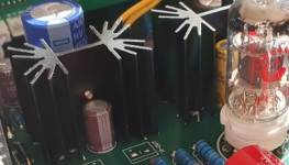
Also please have a look at the design imperfections as seen (measure temp of heatsink and caps) and solder a few Phoenix MKDSN connector blocks where now cables are soldered:
Now you can amplify and attenuate again like voltage droppers do but the most efficient and correct way is to limit GAIN as suggested earlier on.
Also please have a look at the design imperfections as seen (measure temp of heatsink and caps) and solder a few Phoenix MKDSN connector blocks where now cables are soldered:
Attachments
Last edited:
I'm sorry I did not understand the problem before so my suggestions were probably annoying- in all of my study of your post I somehow missed the first couple of words. I guess I would modify my suggestion to "buy a different pre-amp with lower gain".
Honestly, I would sell the pre-amp, or use it elsewhere, rather than modify it. The problem is not only the 10X gain, but the design itself.
I assume that the Chinese version of the Carey circuit is at least somewhat faithful to the guts of the original schematic shown below (sans phono pre-amp and 6CA4 rectification, replaced by noisy silicon diode rectification and a fancy relay-stepped-attunuator volume control instead of the potentiometer.) The nasty thing about this if you look at the center part of the schematic below, the volume control at the beginning of the circuit. The solid state high voltage rectifiers induce noise, and amplifier circuitry itself has a fixed amount of inherent noise even with the filament regulators, and a lot of this noise is being amplified by 10X and dumping right out of the output. The only signal you are interested in, the audio, is presented beautifully by your source at relatively low impedance, full line level or greater to the input, only to be attenuated down to a tiny signal, so small that even after 10X amplification it is back to a fraction of line level, so the amplifier does not blast your ears off. In other words, this design outputs maximum noise for minimal signal, and at much higher impedance than the original source, and it can't be fixed. If you were to add additional attenuation, the problem becomes even worse, because the signal presented to the pre-amp tube is even smaller compared to the fixed noise. It might be unacceptable.
BTW, the 12AU7 on the left, that uses "B+2" is your voltage gain stage, using two triodes in parallel, then the 12AU7 on the right that uses the "B+1" is your cathode follower buffer using two parallel triodes that has unity gain and is trying poorly to lower the output impedance of the pre-amp output signal so it can drive the cable and the input impedance of the power amps. Tubes have high voltage gain, but very little current gain, so they have to play these tricks to be able to drive even a moderate load. The output impedance of the buffer is so weak that you cannot place a volume attenuator at the output, which is why it is at the beginning. The output impedance is miserable compared to the output impedance of the original source.
By the way- I would heed jean-paul's advice about the undersized heat sinks for the filament regulators. Not only are they small, there is no accomodation for circulating air. I would expect that over the span of a few hours they will become quite hot- the four tubes will be dumping heat into that enclosure exacerbating the problem. You might run it with the case on and check every few hours just to make sure.
I probably should have added that a tube pre-amp design like this one originated in a time when typical sources had much lower signal amplitudes, and much higher output impedance, such that pre-amplification was needed, as well as buffering to get through the tone control circuitry and still present a decently low output impedance to the power amp. Sources have improved significantly, with much lower output impedances (1K or less) and output amplitudes have increased greatly to around 2Vrms (5.6V peak to peak), while many power amplifiers have full output amplitude at 1Vrms or less at the input.
So, for modern high amplitude sources, you need more attenuation than amplification. You can now get away with a switch/relay based source selector, and a relay/stepped/potentiometer attenuation and you have all of the functionality you need. You could, for instance, take the entire tube PCB out of circuit- Run the output of the selector/attenuator (that would normally go into the tube amp) to the main pre-amp output. The functionality should be the same- you can digitally select source, and control volume, without significant noise and without the 10X gain. Might be easy enough for a quick try (if you are comfortable soldering).
So, for modern high amplitude sources, you need more attenuation than amplification. You can now get away with a switch/relay based source selector, and a relay/stepped/potentiometer attenuation and you have all of the functionality you need. You could, for instance, take the entire tube PCB out of circuit- Run the output of the selector/attenuator (that would normally go into the tube amp) to the main pre-amp output. The functionality should be the same- you can digitally select source, and control volume, without significant noise and without the 10X gain. Might be easy enough for a quick try (if you are comfortable soldering).
rotel75 mentioned that he likes the sound of that valve pre-amp, which I understand completely, considering that a cold, sterile, unpleasant digital amp ( 🙂 ) is used after it.
An FW clone F4 amp, with that valve preamp driving it as-is, would be an absolutely wonderful combination.
An FW clone F4 amp, with that valve preamp driving it as-is, would be an absolutely wonderful combination.
When a few get to the point there is always someone making it a different issue and mentions a completely different situation preferably with an equally non standardised unusable thingie aka “marrying a donkey to a parrot”. Thereby mitigating the lack of any standard in the glowing world.
Because that is what the issue is.
If the average audio DIYer would think and work like this none of our equipment we build could be interchanged. Me building a 10V rms DAC and you building a 0.1V input sensitivity amplifier is not strength. It is warm glowing stupidity.
Because that is what the issue is.
If the average audio DIYer would think and work like this none of our equipment we build could be interchanged. Me building a 10V rms DAC and you building a 0.1V input sensitivity amplifier is not strength. It is warm glowing stupidity.
Last edited:
Solve issues, don’t create more. Works fine when solving other peoples problems. Reread posts and see if the diagnose and remedy are OK and exactly to the point in the time I put in OP’s issue. My time.
It is not life at all, it is material stuff that is just discomfort when it does not work OK. OP got an answer but he may take your advice and build an F4. It is like having a tattoo when needing a bandaid.
Thank the spaghetti monster that life does not work like audio 😉
It is not life at all, it is material stuff that is just discomfort when it does not work OK. OP got an answer but he may take your advice and build an F4. It is like having a tattoo when needing a bandaid.
Thank the spaghetti monster that life does not work like audio 😉
Last edited:
jean-paul is an acquired taste, like a stiff shot of dry gin, but I am getting used to him. Always entertaining and usually enlightening. Much respect.
- Home
- Amplifiers
- Class D
- Fosi Audio V3 mono, less gain how?