Working on the power supply of a T2500-1bdCP. Would anyone know why Fosgate would use 47 ohm gate resistors on three of the mosfets and 60 ohm on the other nine? I think it's original. Don't think it's been worked on before.
Attachments
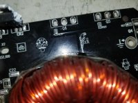

Rebuilt the power supply driver board and replaced SMD drivers on the main board. Drive signals are good and equal to all power supply mosfet gates. Gate resistors are all good. Loaded each transformer with two mosfets. One power supply mosfets run cool at idle. The other runs hot. No outputs or rectifiers in the amp. Draws 3.6 amps at idle. Is there another reason, other than the transformer, that the mosfets would run hot with no load on the secondary?
With at least one FET installed for each of the 4 banks, connect only ground and remote. Do you have a good drive signal on each of the gate legs of the FETs (probe near body of the FET).
Are all of the gate resistors within tolerance?
Are all of the gate resistors within tolerance?


Lower the gate resistor value to see if that helps. If the waveforms were taken from the leg, after the resistors, it appears OK but it's obviously not.
When the B+ is connected, does the duty cycle decrease?
When the B+ is connected, does the duty cycle decrease?
Yes the waveforms were taken at the leg after the resistor. Changed the gate resistors to 47 Ohm. Still getting hot. Yes the duty cycle decreases.
To confirm, do the FETs heat up with the reduced duty cycle?
With the reduced duty cycle, how long does it take for the FETs to get too hot to touch for more than about a second?
With the reduced duty cycle, how long does it take for the FETs to get too hot to touch for more than about a second?
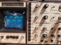
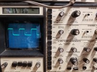
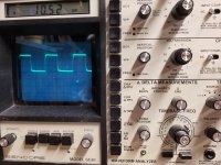
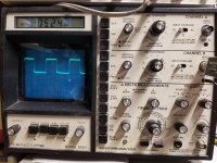
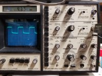
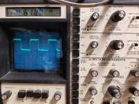
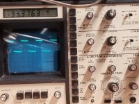
The left image looks like the FETs are in the supply but the frequency should be closer to 25k like the right image (which looks like either the FETs are out of the circuit, or there is no B+.
- Home
- General Interest
- Car Audio
- Fosgate T2500-1bdCP