I own (2) PA-250 FOSGATE branded amps, one with the original box/wires and 2 knob pre amp box. I also own one that came with a PR 2100pre amp only. I also own a PR-2100 Type II EQ box. The EQ boxes all appear to operate fine. One PA-250 WORKS but only on ONE channel sadly. I notice the IC chip FE133, upon operation ONE of them gets HOT, the other no real heat. Other than that I cannot find any other noticeable defects. MY OTHER PA-250 Has an EXPLODED.... 68k 16v, "TICK".... I think thats a Capacitor. Sorry I am Extremely Dangerous, I know that little. Regardless, I have these and hope to one day see them operate once again in 2022. It pleases me that I see Perry Babin here in this thread as I have intentions of purchasing that amplifier course. Glad to see these amps might have some HOPE. Be in touch, BDBD//2022
Hi, one more thing, I would like to use these EQ boxes on OTHER THAN Fosgate amps. FOSGATE Amps I remember from the past as being a bit of a crap shoot but the EQ sections appear rock solid and sound very nice even today. I notice a 18 volt voltage supply to them from the AMP... 18 volts?.... I wonder if these would operate on 14.3 volts. Also where to start... How to power these up somehow. Once I figure out how to power em up I gonna do the DIN CABLE thing..... Have not soldered any DIN CABLES since the late 80's It seems.... hmmmmmm. BDBD/2022

Correct. I used to do a couple things to make these amps reliable. One, drop the 18 V rails to 15 volts. Replace the exploded tantalum with the highest rated voltage tantalum capacitor you can. Drill and tap the mounting holes in the heat sinks to 4-40 screws. You may have to replace the power transistors as the case flexes a lot and the leads break. Changing to a 4-40 screw makes the case solid.
I can't tell you how many I rebuilt back in those days. I learned early that the flimsy cases were a basic reliability issue, that tantalum another. Other enhancements were changing the op amp to something good, and using a resistor to provide bias for the bias network instead of drawing it from the op amp. These designs were designed to be cheap, you an really improve them by putting just a little work in. Remember, they saved every component they could, and every manufacturing step. Other amplifiers of that era used either 4-40 screws or M3 screws (about the same).
I can't tell you how many I rebuilt back in those days. I learned early that the flimsy cases were a basic reliability issue, that tantalum another. Other enhancements were changing the op amp to something good, and using a resistor to provide bias for the bias network instead of drawing it from the op amp. These designs were designed to be cheap, you an really improve them by putting just a little work in. Remember, they saved every component they could, and every manufacturing step. Other amplifiers of that era used either 4-40 screws or M3 screws (about the same).
I recently purchased a PR-252 that has the 4-40 screws, does that mean it's one of the ones you worked on, or did Fosgate eventually change to those as well?
Hi JTFX,
I can't remember all the model numbers that Fosgate used. I worked on so many they could surface just about anywhere! Fosgate very probably changed to 4-40 screws as the ones they used were useless in keeping the case from flexing. They were self-tap and maybe #2 screws. I saw them stripped and loose / missing often enough.
I removed and cleaned the heat sinks, drilled and tapped plus deburred. So one I did would look neat and factory I guess. The tantalum in the supply would have been an Electrolytic, or a much higher voltage Tantalum. They would literally split and burn leaning soot on the PCB and adjacent components. I also moved the driving tap on the diodes in the output section to the mid-point and add a resistor to the other rail. The op amp then drove a balanced load. I can't remember which op amps I was using, probably a J-Fet input as they were faster and less noisy. I always cleaned the flux off as well.
Well after over 8 years the PR2100 is up and running. I sent it to Canada to get it repaired and back hopefully before walls are built surrounding the USA!
Special thanks to Chris. Great guy.
Special thanks to Chris. Great guy.
Hey, you got it already?
Fantastic!!!! Let us know how you like it once you get used to it again.
Yeah. Useless walls. This continent is really one big family.
Fantastic!!!! Let us know how you like it once you get used to it again.
Yeah. Useless walls. This continent is really one big family.
I have gotten my 2100 serviced also and working!!! sounds beautiful 🙂 wondering what you all know about this mod (see pic) hmm do you think this is the type II update they talk about? I grabbed this on a old thread and he says they have serviced 1000s so I got to believe it's is legit..
Attachments

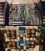
I do not know sorry. My example is the only one I have ever seen. I do know the one I have has an update(or possible from new) on the underside of the circuit board. A resistor and capacitor on each corner. Something to do with the amp coming on in cold weather? Perhaps Anatech will respond to this?
Check out this cool youtube video someone put up few year back. It even has pics of my amp in it.
Check out this cool youtube video someone put up few year back. It even has pics of my amp in it.
Hi moxysoft,
I was restoring the PR2100. Upgrades to this class B amplifier aren't the same as the later models. Most of what we saw were the PR250 model, some type II.
There were two really major issues with the type I. The case screws were tiny, self-tap types that allowed the chassis to flex, breaking all the power transistor leads. Drill and tap for 4-40 screws. I learned you had to replace all power transistors or you would have the odd one breaking later. Also the regulator transistors ran far too hot, so a larger case style with added heat sinks are needed. Servicing this one reminded me of this issue.
Some amps did have an issue turning on in very cold weather. I think the fix used to be replacing the value of resistor across the diode feeding the B+ out lead (turn-on) with a lower value one sorted that out. It also depended on the load (radio) you were using. I didn't do that simply because we only modified units that had reports of a problem.
Then there is the famous tantalum short / burn issue. This was the capacitor near the transformers. Install one rated at much higher voltage, or an electrolytic designed for switching supplies, or a new Poly-Aluminum (which is what I did). There are other tantalum capacitors that were also replaced. Upgrading the op amps is of little help. Maybe in the preamp, but it won't buy you much - if anything. The distortion of the main amplifier dominates, it isn't horrible. Then there is the distortion in the head unit (tape and FM) that easily exceeds the amp and preamp. Then of course ... the car speakers and environment.
Upgrading these amplifiers (or any amplifier) has to be done intelligently. You can't waste the client's money with the promise of better performance unless you can prove it. The average person is very susceptible to the suggestion that something is better, and they will hear it. Emperor's new clothes. What was done was the new outputs, invertor and driver transistors were matched so they shared current equally. Matching the invertor transistors greatly aids reliability. Since there are no emitter resistors, matching in the output stage can be very important as well. If it wasn't class B, the lack of emitter resistors would probably cause all of them to fail. None of these improvements show in pictures.
"Back in the day" I rebuilt so many of these I lost count. My large shop was in the GTA in Ontario and it was a very active car audio scene. We got them hacked, "improved" and everything in between. Returning them to factory stock while looking after those problems was the best course of action. You wouldn't believe how many were mounted on the subwoofer box! Add in an off-road vehicle and we had to find ways to keep them in one piece.
I see you found my short video on the 2100!! 🙂 ... anatech I appreciate what you said it seems like modding these amps was like the wild west everbodies got a different solution.. I guess I will stop trying to find the one magical answer for these. If anyone has documentation I still would love to see it or notes! I will leave you with a portion of my collection of theOG Fosgates ;-)

Hi moxysoft,
I did, but don't have time to watch it. I'm working.
It was like the wild west. I talked to the distributor, who I had a connection with. They didn't help many people. I do my best to do practical things of real value. Spent a lot of time cleaning up disasters. I did try to improve performance in these and the MKII series was better in that regard.
We also had the MGT 2100 and 2200 amplifiers in circulation. They had their issues, but really put out a lot more power despite having the same ratings. Nicer amplifier design, but the power supply was noisy (lower frequency operation too). The supplies in those were all +/- 33 to 34 VDC, class A-B, not class B.
For clean sounding amps driving realistic loads (4 R minimum), amplifiers by Alpine, McIntosh, Nakamichi and a few others were the best. Then we had Linear Power if you wanted stupid power (one had +/- 90 volt rails!). They weren't made that well, nor did they sound that good.
- Home
- General Interest
- Car Audio
- Fosgate PR-2100 help