My suggestion of the RCA input grounding is much easier and less expensive than changing out the caps. Literally unsolder the shields to the RCA jack from the grey wires. Then solder the ground to the main ground bus.
Generally, I agree that a change in gnd wiring may help, but I am afraid instructions
in your post 98 are not clear enough and the picture does not show the whole story.
in your post 98 are not clear enough and the picture does not show the whole story.
The grounding on these was not optimal if I remember correctly. It was also system dependent with the preamplifier. Ground isolation with system ground and signal ground may also help.
That's interesting, Wayne. I have the matching preamp, though I haven't used it with the amp for years, as I preferred the Threshold Fet 10 with it so can't recall their performance/sound as a set.
What would you suggest for ground isolation - something like 10 Ohm resistors? Or maybe an earth loop breaker ala Rod Elliot?
What would you suggest for ground isolation - something like 10 Ohm resistors? Or maybe an earth loop breaker ala Rod Elliot?
Yes, a ground loop breaker between chassis ground and analog ground can help too. Look for where chassis ground is connected to central ground bus on PSU. Add a CL60 NTC there (paralleled with a 22nF film cap) to isolate the chassis (dirty ground) from the PSU analog (clean) ground.
Rewiring the signal input ground is a simple concept. Cut the ground from RCA shield to the PCB, connect the RCA shield to central ground bus on cap bank. We are trying to remove the ground path from the RCA shield to the PCB, and then to the PSU ground through a long path that might be high impedance, and hence develop a ground loop hum. This may not work. In which case, return it to the original configuration. A lot of hum and ground loop debugging is trial and error.
This might be helpful: Audio Component Grounding and Interconnection
Last edited:
The CL60 in lieu of the resistor across the bridge?
Thank you for the link to the grounding discussion!
Thank you for the link to the grounding discussion!
Th CL60 replaces a high current diode bridge wired as anti-parallel and 10ohm resistor as a GLB. The diode bridge provides a nominal 1.2v standoff for ground loops to go through the 10ohm and conducts when there is a fault that exceeds 1.2v. The CL60 NTC provides a nominal 10ohm when cold (for all voltages) and if there is a fault it heats up and is about 0.5ohm for earth safety ground. They both work but NTC is simpler and captures higher voltage spikes.
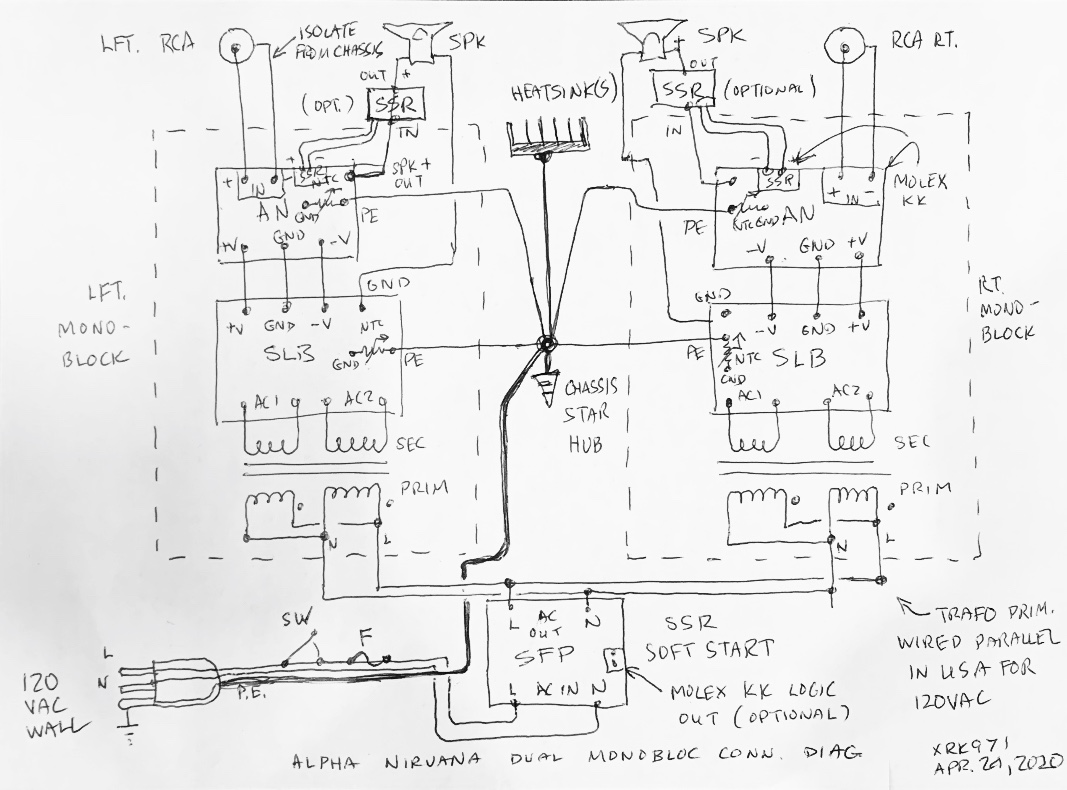
For my amps, I typically have an NTC on each PCB between the analog (clean) ground and the protective earth safety (dirty) ground. These dirty grounds connect to a star hub on the chassis and from there to the earth ground on the IEC inlet to the wall plug. Here is an example of how one of my amps is wired. This one has dual mono setup with separate trafos and cap Mx PSU’s.
We have to thank member @David Davenport for the write up. Very nice piece of info for the community.
Last edited:
Thanks a lot, XRK! Although this is dastinger's thread, not mine, and my amp is quiet, the input you and others have provided has been interesting and useful to me.
I completely agree. The amount of knowledge in this forum is amazing!
I'm gonna go through this grounding solution again on the weekend. I need to make sure of what I'm doing and need time to read properly.
I'll keep you guys posted. Again, thank you everyone!
I'm gonna go through this grounding solution again on the weekend. I need to make sure of what I'm doing and need time to read properly.
I'll keep you guys posted. Again, thank you everyone!
I hope you find the source of the hum. I know that when I first started building amps, the hum and ground loops was sort of hit or miss. Now, with proper attention and concepts of keeping dirty and clean grounds separated by NTC GLBs and the use of star hub topology - my success rate is much higher. The biggest piece of advice that I got from JPS64 was “you have to think like an electron!” If you were an electron, you are lazy and you want to take the path of least resistance. So make sure there are no inadvertent connections to either “chassis ground” or “analog ground”. All connections to any ground must be planned and deliberate because they are not all the same and it matters where they are.
- Home
- Amplifiers
- Pass Labs
- Forté Audio Model 3 Hum