So looking closer , What your saying is to wire , short blue and purple on one side and gray and brown on the 0v side, Wire 115volt parallel and cap the white wire . For the Primary? I tried the parallel and my voltages were wrong? ( the white wire) if you read it from blue to brown or brown to blue?
Maybe the Transformer is defective? Before I think about replacement,
I'm going to try this configuration- So I short Gray and Brown cap white and use Blue and Purple as my 120volt main , The 2 secondary green wires are 29.5 volts going to the Bridge rectifiers with my secondary white going to ground , Right.. Thank You..
@rmoran206
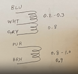
Please use a ohm meter to measure all 5 primary winding wires the resistance among each other and post the result.
Gray - Blue = ? Ω
Gray - Brown = ? Ω
Gray - Purple = ? Ω
Gray - White = ? Ω
Blue - Brown = ? Ω
Blue - Purple = ? Ω
Blue - White = ? Ω
Brown - Purple = ? Ω
Brown - White = ? Ω
White - Purple = ? Ω
Then we can determine which wire belongs to which winding.
Before you connect it to the mains, next step is to determine the polarities of each winding, that will avoid "bigbadaboom" as @Zen Mod mentioned on post #14.
After using 2 different meters one of them being a fluke set on the 2 lowest settings, Primary
200 ohm/ 2k ohm
Gray-Blue 1.5 / 0
Gray-Brown 1.2 / 0
Gray-Purple 1.5 / 0
Gray-White 1.3 / 0
Blue-Brown 1.6 / 0
Blue-Purple 1.4 / 0
Blue-White .3 / .4
Brown-Purple 1.0 / 0
Brown-White 1.4 / 0
White-Purple 1.2 / 0
200 ohm/ 2k ohm
Gray-Blue 1.5 / 0
Gray-Brown 1.2 / 0
Gray-Purple 1.5 / 0
Gray-White 1.3 / 0
Blue-Brown 1.6 / 0
Blue-Purple 1.4 / 0
Blue-White .3 / .4
Brown-Purple 1.0 / 0
Brown-White 1.4 / 0
White-Purple 1.2 / 0

Based on your measurement, it is not two separate winding! Any possibility there's error in measurement?
Japanese sets sometimes had a 0-110-220 primary winding for export market.
Rarely, 0-100-120-220 is found, the 100 is for domestic Japan market.
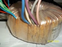
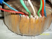
A picture of the track side where the wires are connected would be nice.
Rarely, 0-100-120-220 is found, the 100 is for domestic Japan market.
A picture of the track side where the wires are connected would be nice.
No the measurement are has accurate, I could get on the lowest resistance setting, They fluctuated a little I used 2 different multi meters
Primary // secondary
Primary // secondary
Attachments
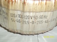
Yes, I had seen 0-100-120-220-240V primary winding in a Japanese preamp, that made 5 wires! However, the measurement in post #24 does not add up.Japanese sets sometimes had a 0-110-220 primary winding for export market.
Rarely, 0-100-120-220 is found, the 100 is for domestic Japan market.
Is this Transformer defective ? If so, I will need to replace it with a 120volt primary and 2 , 29.5 volt secondary's wires and a ground..
Is this Transformer defective ? If so, I will need to replace it with a 120volt primary and 2 , 29.5 volt secondary's wires and a ground..
Probably.
I will need to replace it with a 120volt primary and 2 , 29.5 volt secondary's wires and a ground..
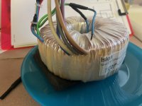
This Transformer goes in a Forte 4 power amplifier..
Where's a good place to start looking, Thank you for your help.
This Transformer goes in a Forte 4 power amplifier..
Where's a good place to start looking, Thank you for your help.
This must be where the chickens come home to roost? Since my transformer came from Nelson himself, I feel honored to offer it to some lucky member toward the most worthy cause.
It measures normally (see pic), although it has not been load tested...
It measures normally (see pic), although it has not been load tested...
Attachments
How much would you want for it, and 2/ 29.5 volts secondary with a ground ?
The Pictures look good..
The Pictures look good..
Last edited:
Nice.
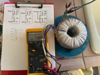
I looked at the picture, can you put wire colors on the schematic?
That should be helpful to OP.
I looked at the picture, can you put wire colors on the schematic?
That should be helpful to OP.
Oh, sorry, I did not look closely at the pictures in Post #34.
The wire colors are indeed marked in small print on the schematic, and there is the same drawing next to the meter.
Now the OP has to work out the landed cost of the transformer after checking his unit again, shipping may be costly compared to getting a unit in the USA.
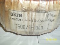
Our Air Force had Iskra trainers ....the word means 'spark' in Polish, they came from Poland.
The wire colors are indeed marked in small print on the schematic, and there is the same drawing next to the meter.
Now the OP has to work out the landed cost of the transformer after checking his unit again, shipping may be costly compared to getting a unit in the USA.
Our Air Force had Iskra trainers ....the word means 'spark' in Polish, they came from Poland.
Last edited:
Good job! @Andersonix 👍
 — Scaled (31%).png")
All the BAD measurement should displayed "O.L." on his meter. I believe OP's transformer has shorted primary windings.🙁
Gray-Blue 1.5 GOOD
Gray-Brown 1.2 BAD
Gray-Purple 1.5 BAD
Gray-White 1.3 GOOD
Blue-Brown 1.6 BAD
Blue-Purple 1.4 BAD
Blue-White .3 GOOD
Brown-Purple 1.0 SHOULD BE HIGHER (1.5-1.6)
Brown-White 1.4 BAD
White-Purple 1.2 BAD
I always short the meter leads before measuring, sometimes they do not show zero, so such readings are to be adjusted.
At such low readings, meter error can occur.
I know somebody who makes ferrite transformers, he has a micro ohm meter, which I rarely need, so I go to his place with the part that needs checking.
Would a series lamp be useful to check?
And was the unit working before changing continents?
Or it failed because somebody was careless and fed it wrong supply?
- Home
- Amplifiers
- Pass Labs
- Forte 4 power amp replacement transformer & schematic ?